
 Schools Tender Snowplough kit")
")
 Conflat D kit")


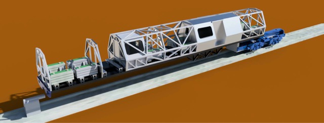
The real POP Train was based at the RTC in Derby and was the full-size testbed for the APT-E and APT-P tilting mechanisms. Unusually, it was built alongside APT-E rather than prior to it. The train was unpowered, and consisted of two cars numbered PC3 and PC4. Each car was made up from a steel box frame, not dissimilar in profile to the APT-E. Ten bulkhead open trellis sections were spread unequally along the length of each car, joined length-wise with more box steel section to form a cage. Rather like a Ducati motorcycle frame, only square section and not rusting on the welds. At roughly one quarter of the length of each car was a covered cabin with double door access from one side, single door access at each end and a large viewing window to each side. One can only assume that these cabins would have been loaded with all manner of technical measuring equipment and / or seasickness medicine cabinets. Each car had an independent outside bogie and shared a single articulated bogie in the centre.

The Model Build – Materials (a bit techy, sorry)
Like any project, access to good photographs and accurate drawings is crucial, and in this case this proved tricky. I was given access to some drawings that appeared to have been drawn from memory rather than from any official source. These were riddled with inaccuracies and assumptions, so were rapidly discounted. I was lucky to have been loaned some drawings that appeared to bear much more of a resemblance to the prototype so these were scanned and scaled to 4mm scale and used as the basis for the 3D build.
The subject of what material to use needed addressing very early on as I basically had a choice of two, both being 3D FDM materials but very different in nature and both requiring a very different approach to extrusion. The model was always going to be thin and spindly so would be vulnerable to heat and moisture damage. As luck would have it, the build commenced during the scorching summer of 2020 with outside temperatures in the UK pushing 30 degrees, so we had ideal test conditions to se what would and would not work.
My FDM material of choice is PLA or PLA+. It has a working extrusion temperature of around 180 to 210 degrees Celsius on a bed temperature of around 55 degrees Celsius. In normal circumstances, the heat can be barely detected when sitting in close proximity. However, PLA has a low glass transition point of around 85 degrees (the temperature at which it changes state from solid to liquid). While this may sound high, in reality you will start to see deformation on thin prints around 30 degrees. I didn’t wa’t Mark’s model to melt on the way to a show in the car so I started to investigate the use of PETG.
PETG has a working temperature of around 240 degrees on a bed temperature of 75 degrees. Now, in the heat of summer this makes for an uncomfortable time at the bench but it does produce a really strong print that is resistant to any temperatures the UK is likely to suffer. Two test pieces were produced of the POP bulkhead and placed in a windowsill for 24 hours. The PLA warped and the PETG remained straight. The joy was shortlived as I had no idea at this time what an awful material PETG is to work with. PLA was selected for the solid “thick” components such as the cabins, chassis frames, internal details, buffer beams and bogies, and PETG deployed for the cages.
The Tilt
With the material chosen, attention turned to the tilting mechanism. Its got to tilt after all, right?!
I will get this bit out of the way quickly; I really do not like Hornby’s original tilt mechanism on the APT-P. It needs sharp radius curves in order to be effective. There, I said it.
I wanted something that would show signs of tilt through large radius curves and pointwork. Even though both of my boys were starting to get too old to play Lego, we still had a large box of Lego Technic parts squirreled away in the loft and I started to think about using bevel gears to translate vertical rotation of the middle bogie into lateral rotation of each car.
A working prototype was drawn up, 3D printed, and fitted with Lego Technic gear trains and demonstrated to Mark at the infamous “get Kim back in to modelling”, sorry, running session at Richard’s house.
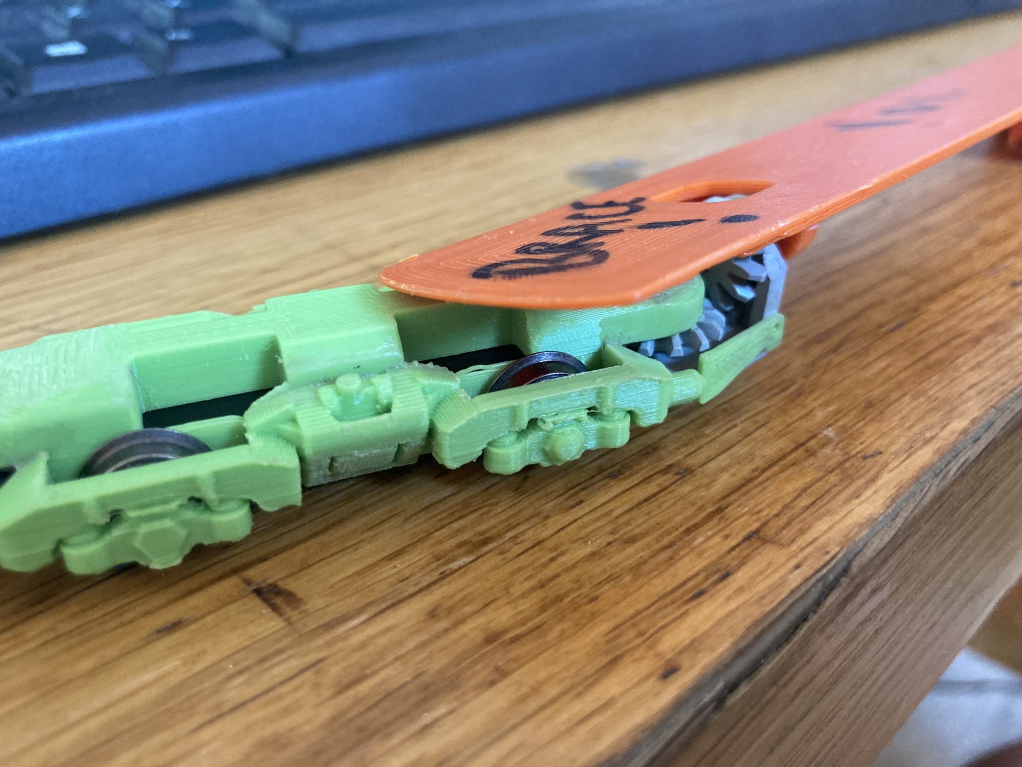
It got the thumbs up and work on the CAD build proceeded until the hot weather calmed down….
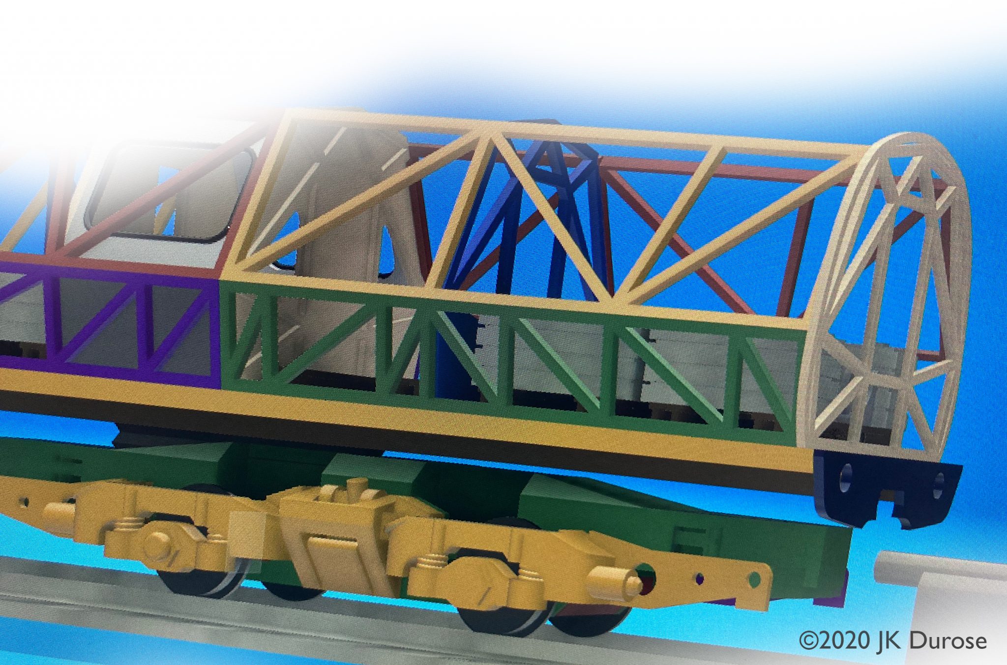
Completed CAD drawing, signed off for printing!
Once the design was complete, what followed was around two weeks of evenings spent component printing. PETG is not a nice material. Without getting too technical, the hot temperatures and fluidity of the molten plastic cause huge retraction stringing issues and the material is very reluctant to adhere to the print bed. Once complete, the PETG was returned to it’s airtight storage box, replaced with PLA and was never invited to come out to play again.
Assembly
With all of the components printed, I needed to find a way of building the cages straight and true so quickly drew up 2 jigs that would hold the bulkheads still, vertical and square while I attached the sides with PlasticWeld liquid adhesive. If you have never tried PlasticWeld, seriously you should.
A thoroughly nail biting moment was when it was time to extract the builds from the jigs and happily all went well.
Bogies were fitted with 12mm Romford disc wheels held in place via the axle centre rather than “pinpoint” bearings. Weights were added from suitably shortened Triang wagon weights. It is a difficult model to conceal anything due to its very open framed nature so care had to be taken with weighting the chassis themselves. I did this by building cavities in to the chassis design to house more Triang weights, totally out of sight.
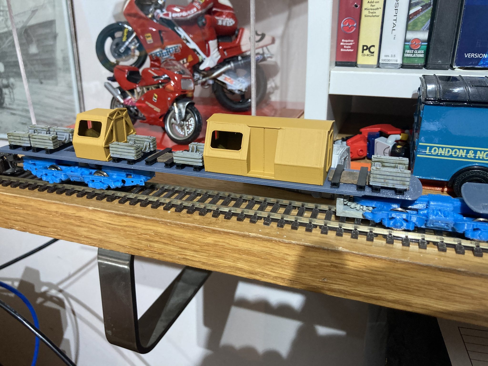
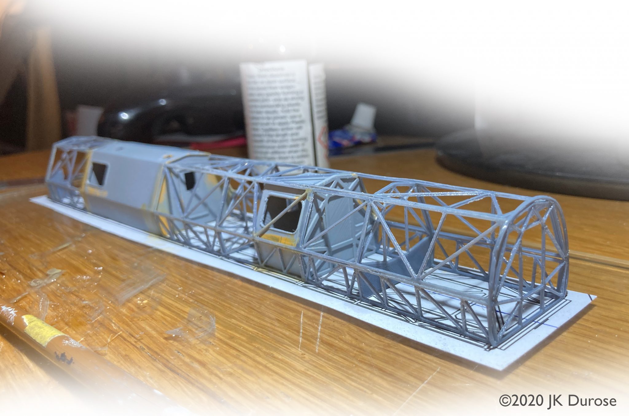
Early prototype build. The cabins were later rebuilt as three-piece components with better results. I also tidied my shelf.
Painting and finishing
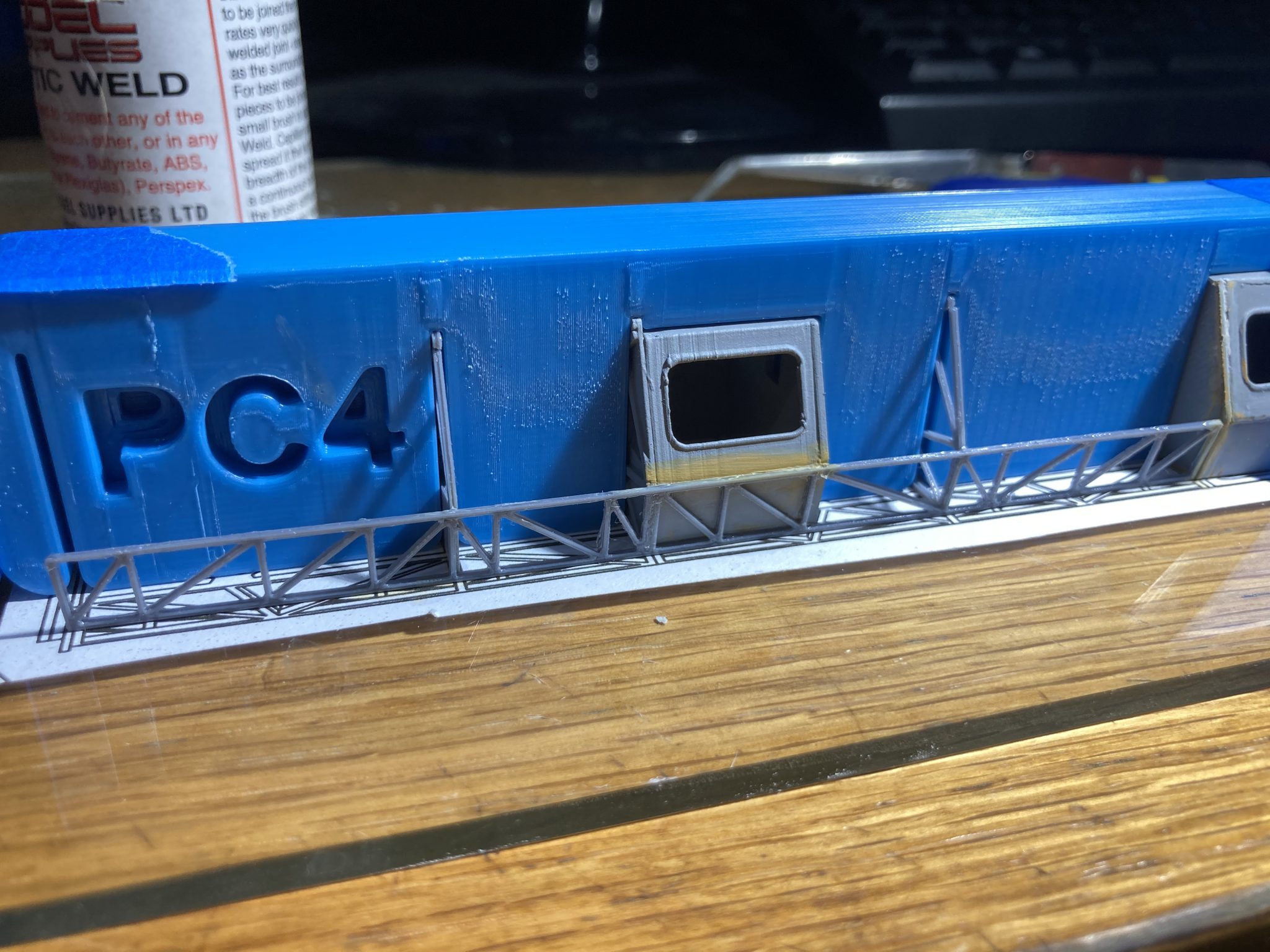
Paint came from the usual Halfords rattle cans. Several layers of high-build primer were applied to smooth out any remaining print layer lines, followed by grey primer and a thin coat of champagne gold.
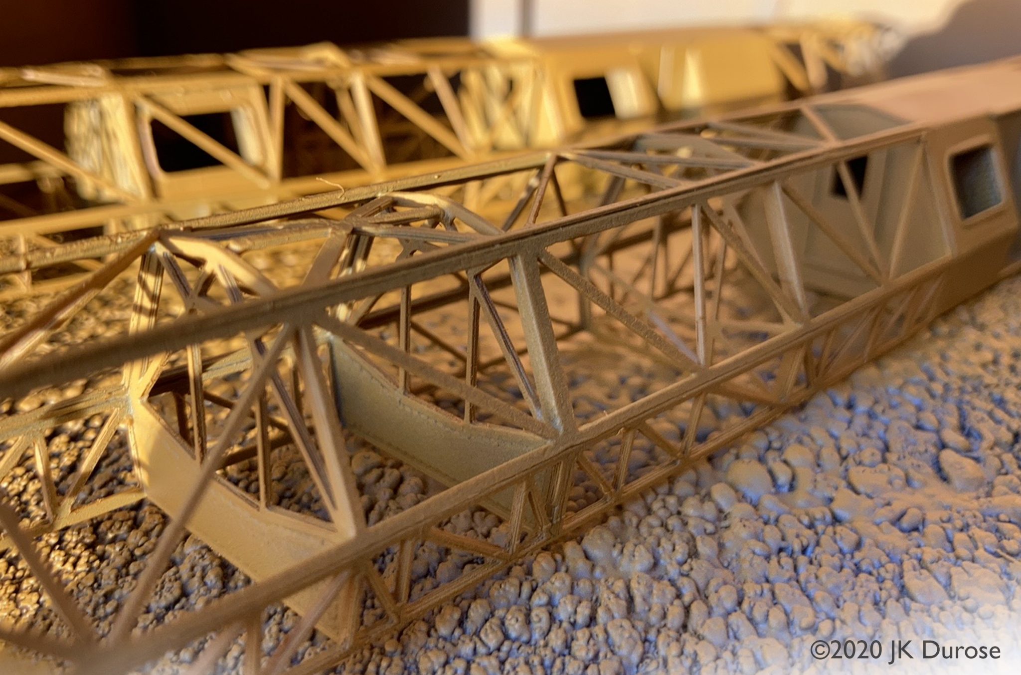
PC3 and PC4 in high build primer. The cages are surprisingly rigid.
Matt aluminium was then airbrushed over the top in a very thin coat to give a subtle “yellowness” to the colour which is evident in the photographs I had sourced.
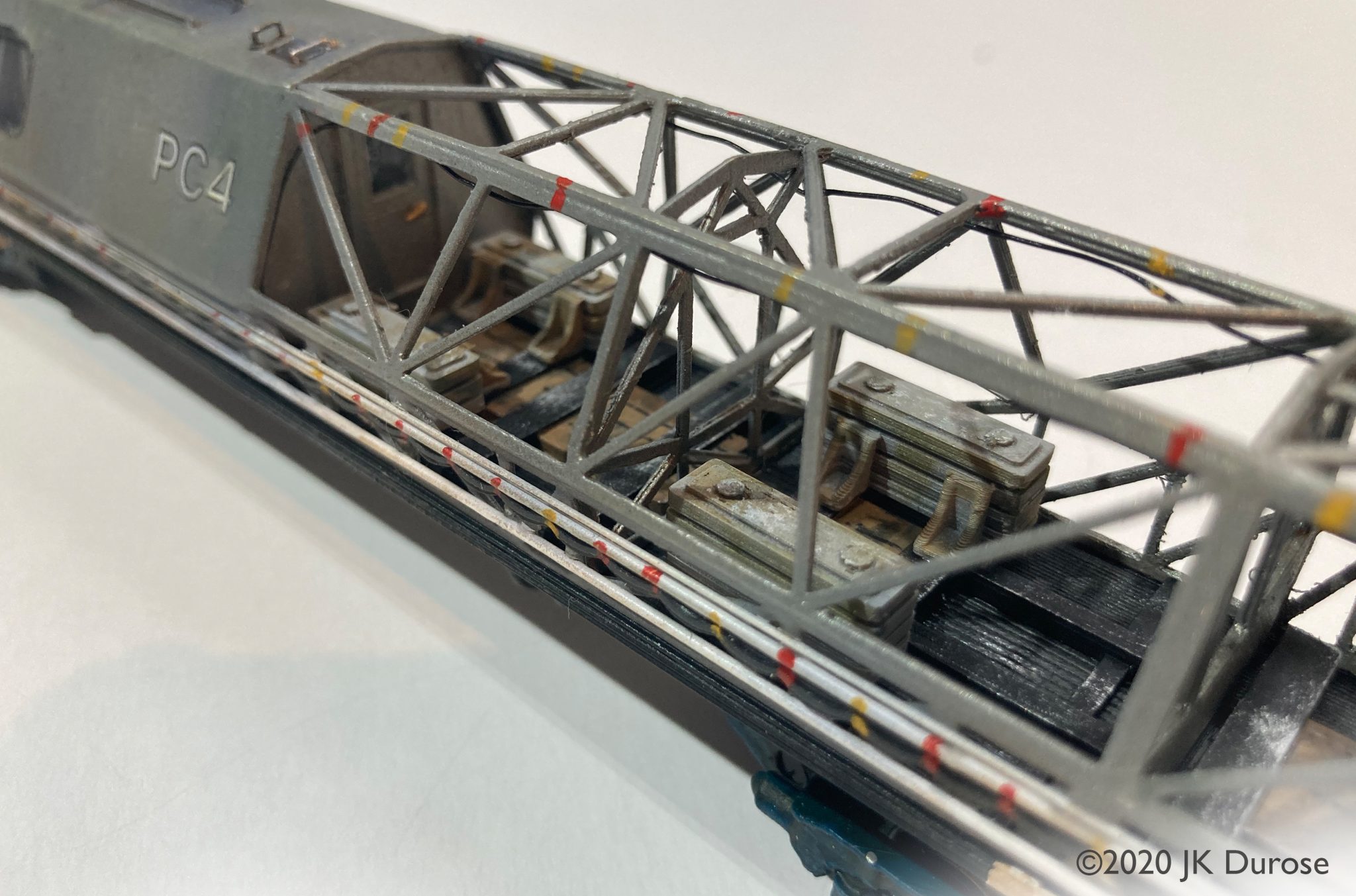
Decals are custom drawn and only really amount to the PC3 and PC4 on each cabin side.
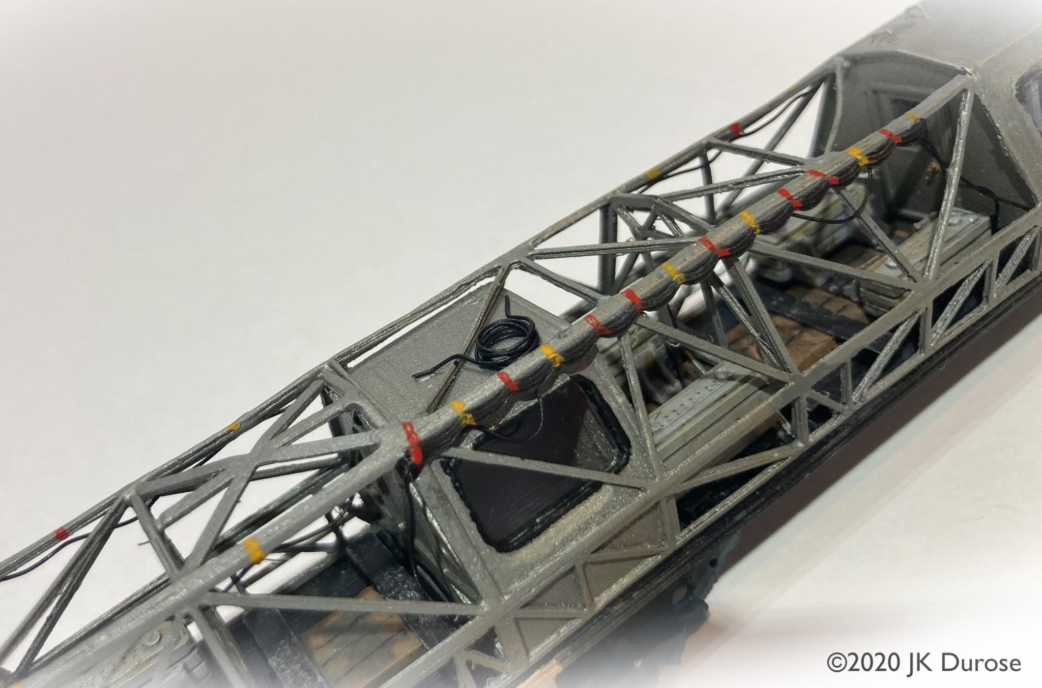
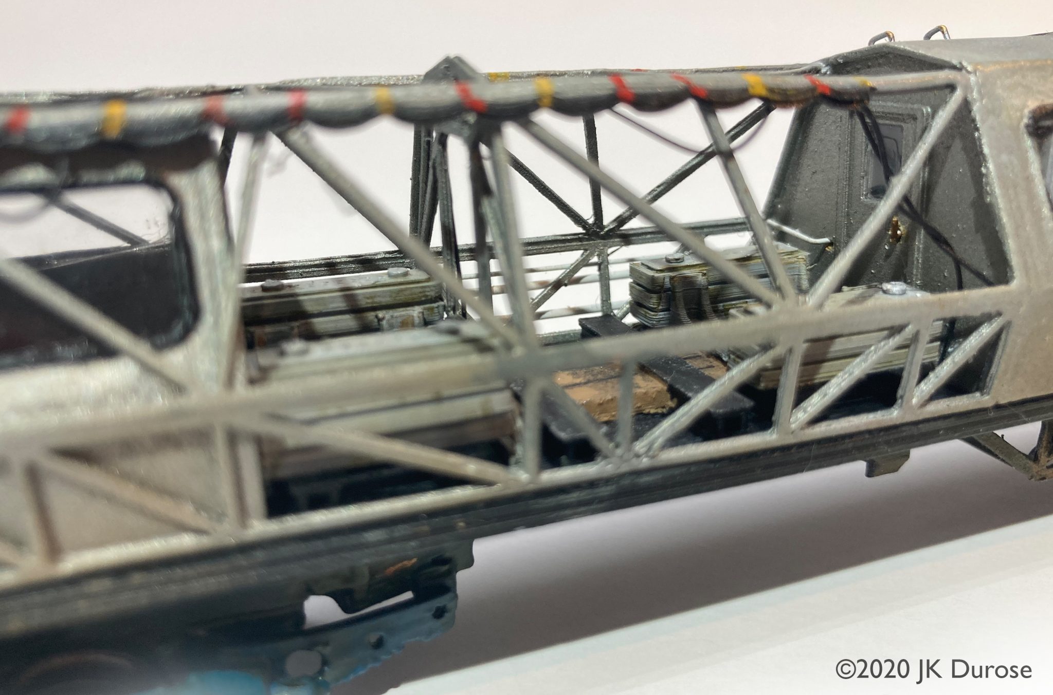
Cable “clutter”, seen in abundance on any photograph was added from pre-coloured black jewellers wire, with runs of coloured electrical tape tethering it to the cage added with a fine brush and acrylic paints.
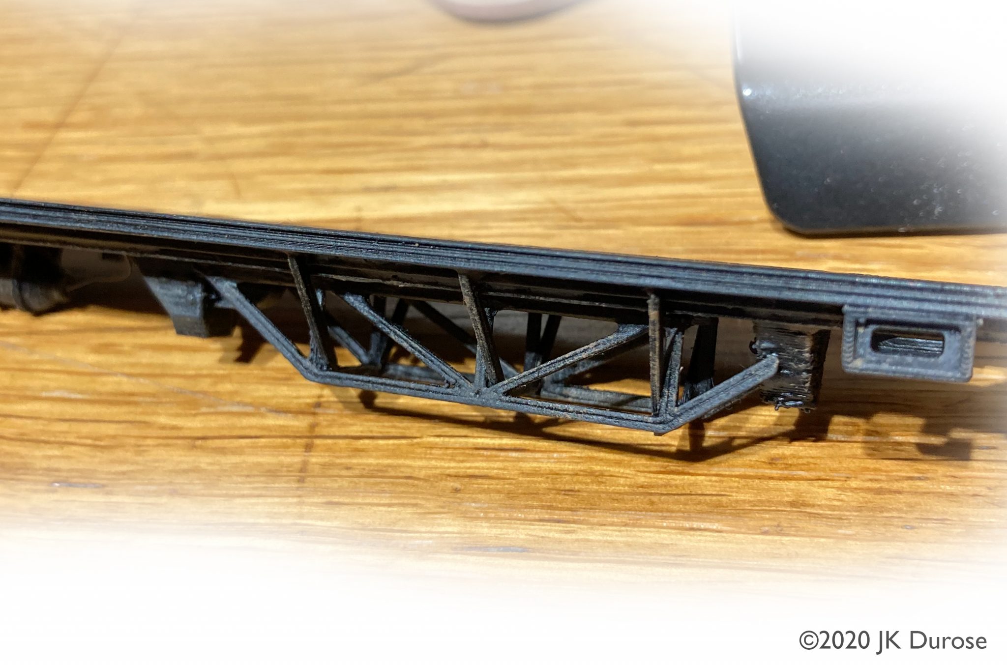
Underframe trusswork and lifting points.
All in all this was a testing and challenging project. I’m happy with the result and it certainly draws questions when running at shows on Mark’s “Welby Lane” RTC layout.
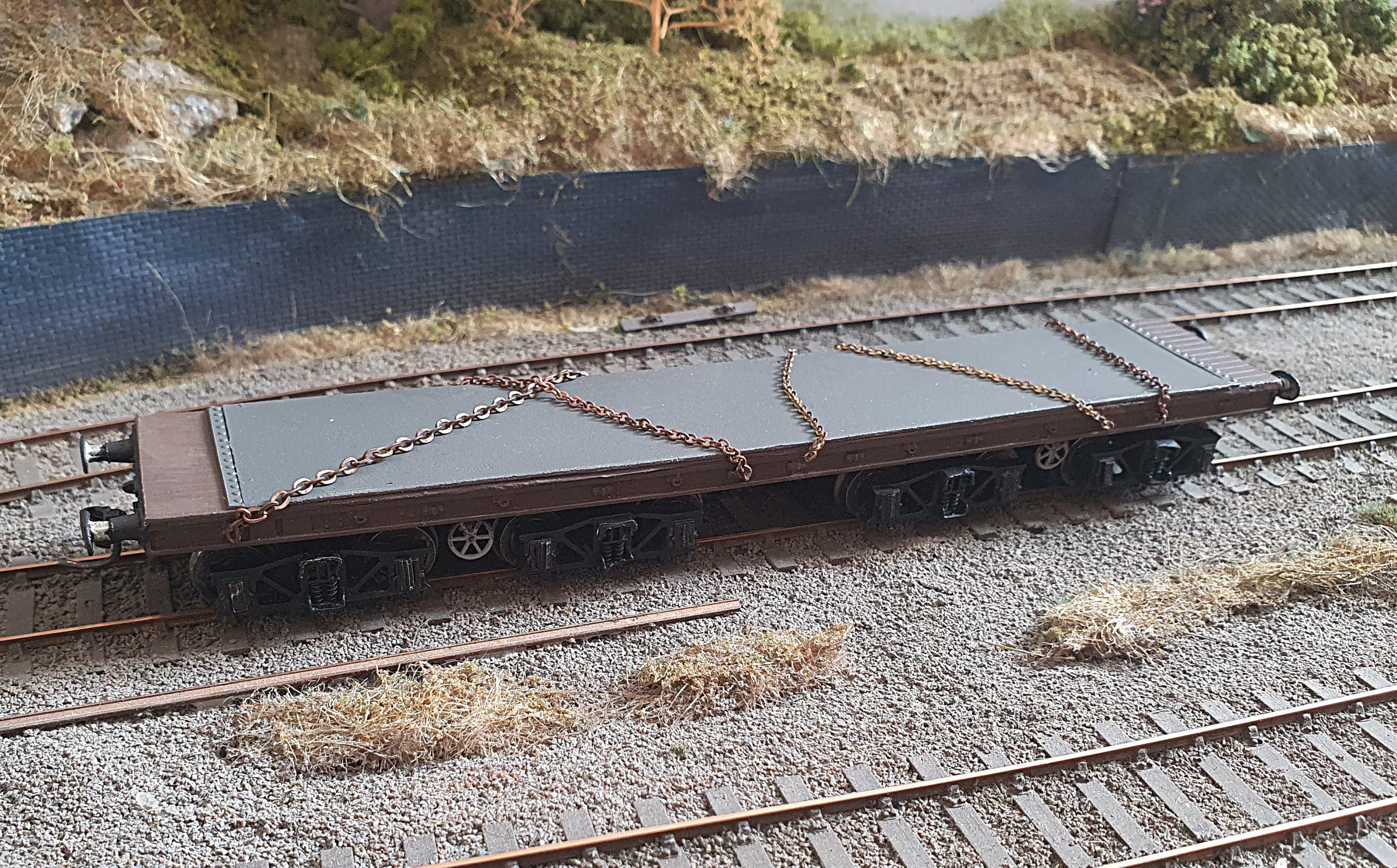
Running plate clutter and planked floor. These were concrete weights used to adjust the weight distribution during tilt testing.
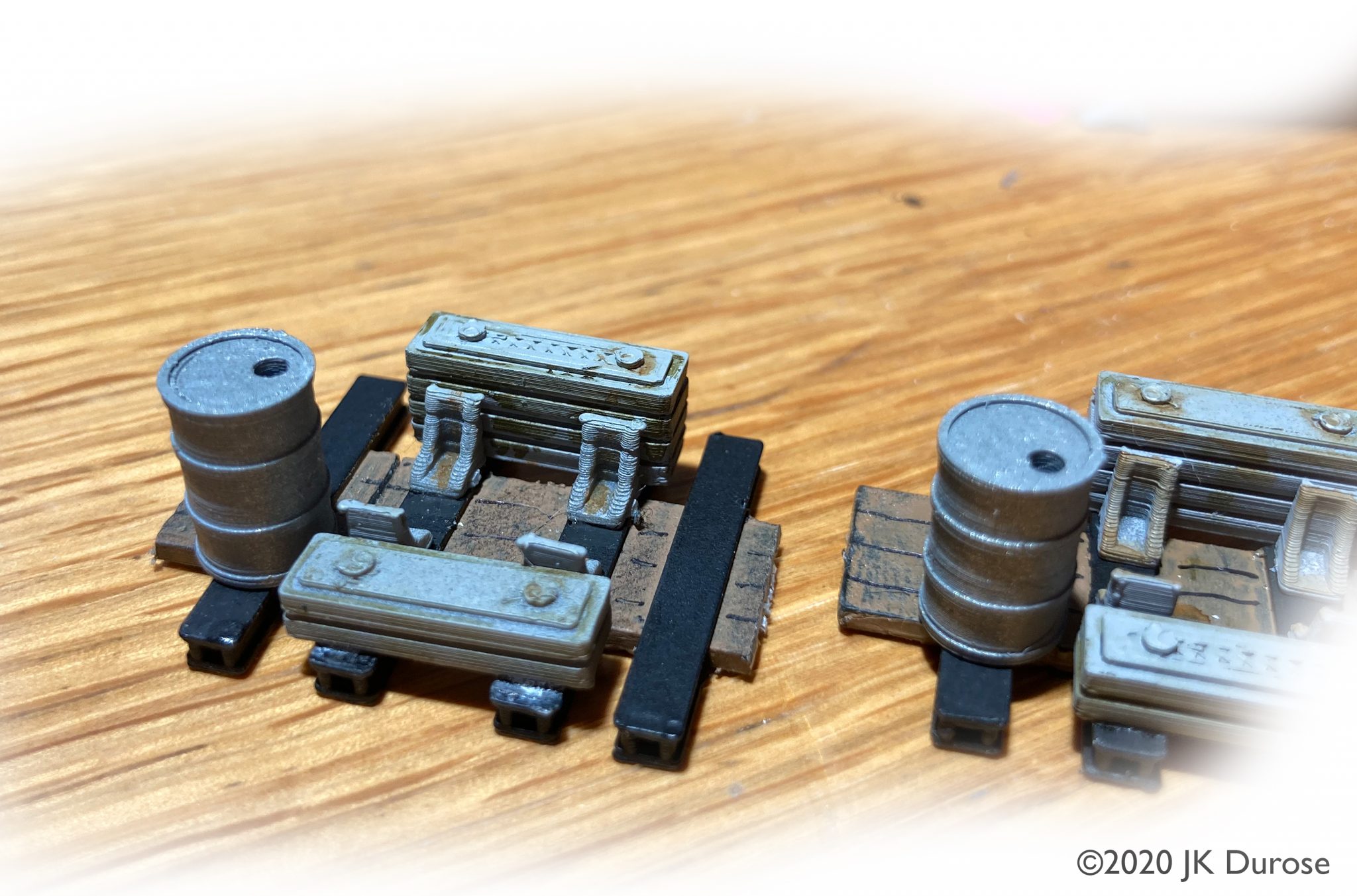
Cross-members, floors, weights and hydraulic fluid drums are all 3D printed separate components.
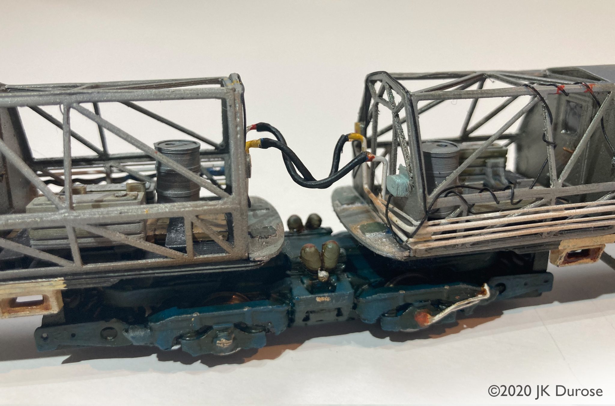
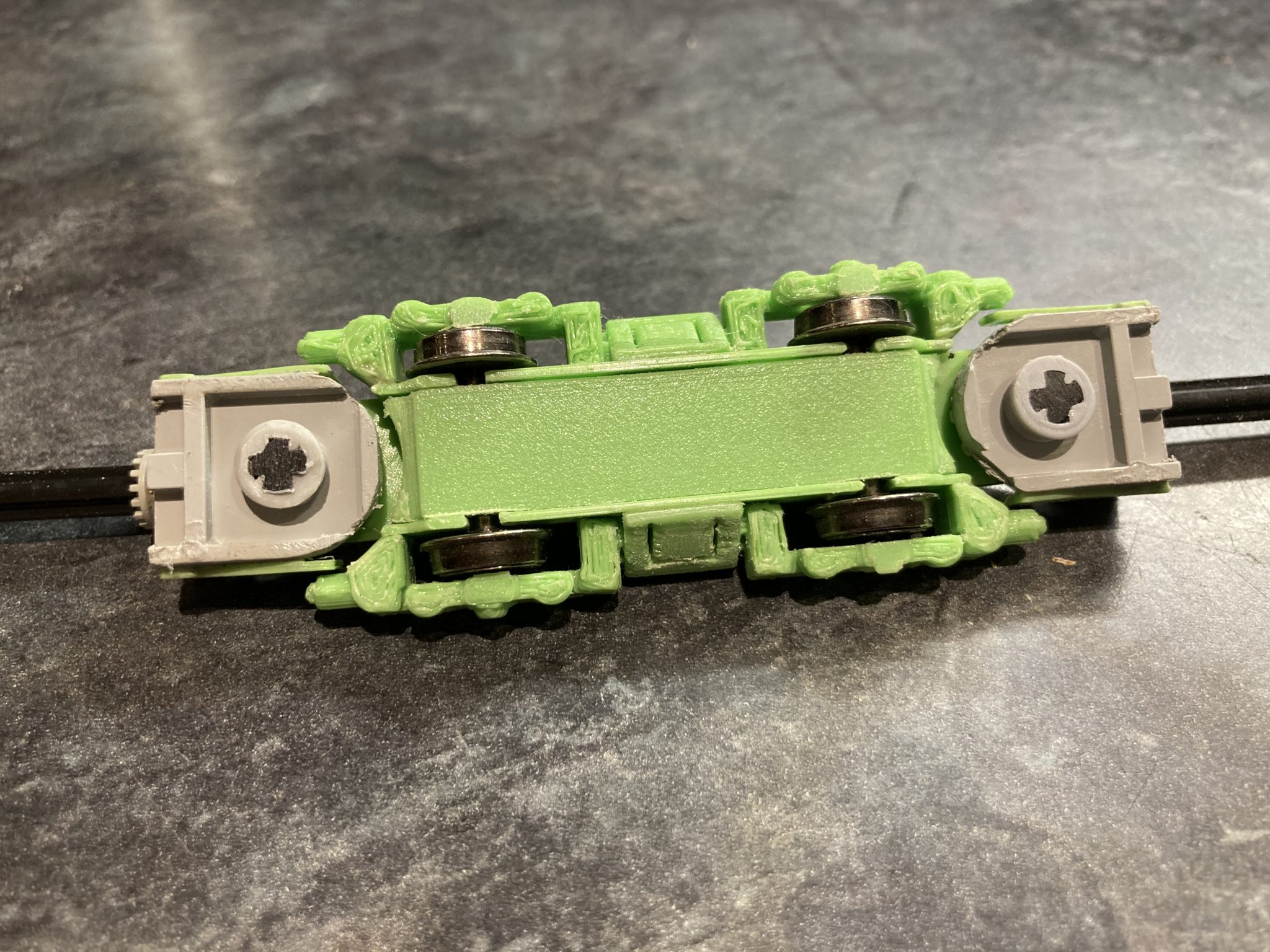
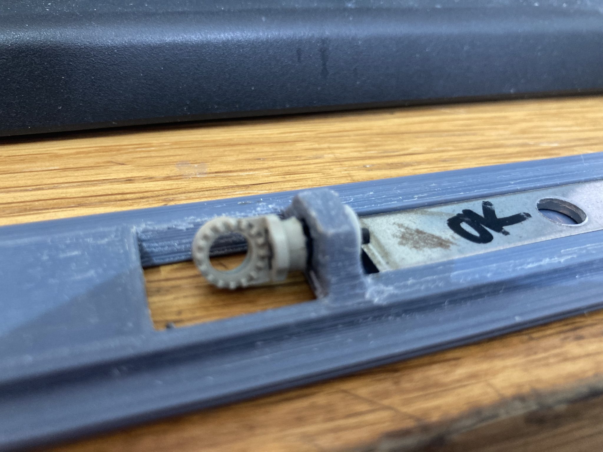
Articulated centre bogie with hidden Lego Technic tilt mechanism.
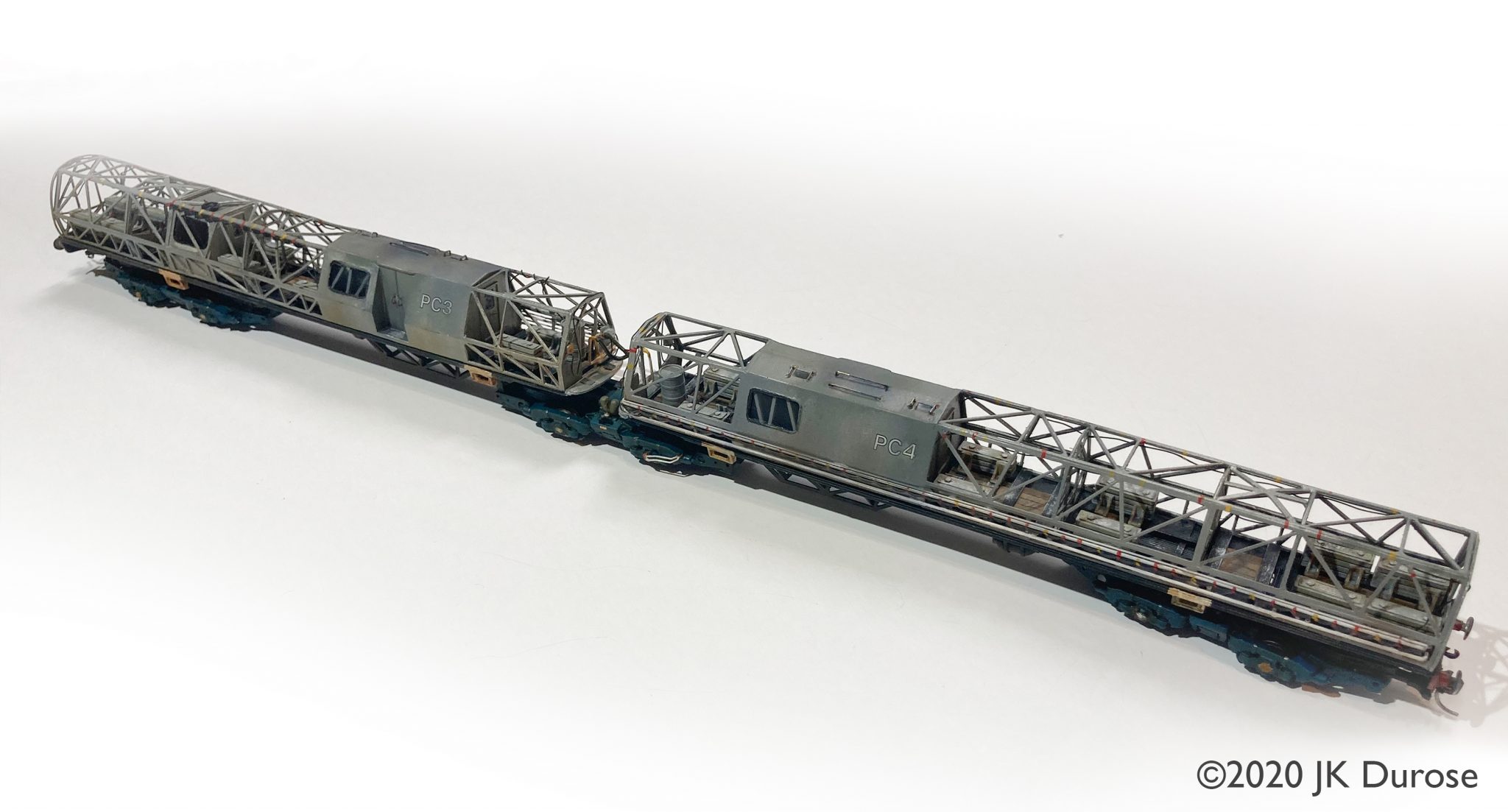
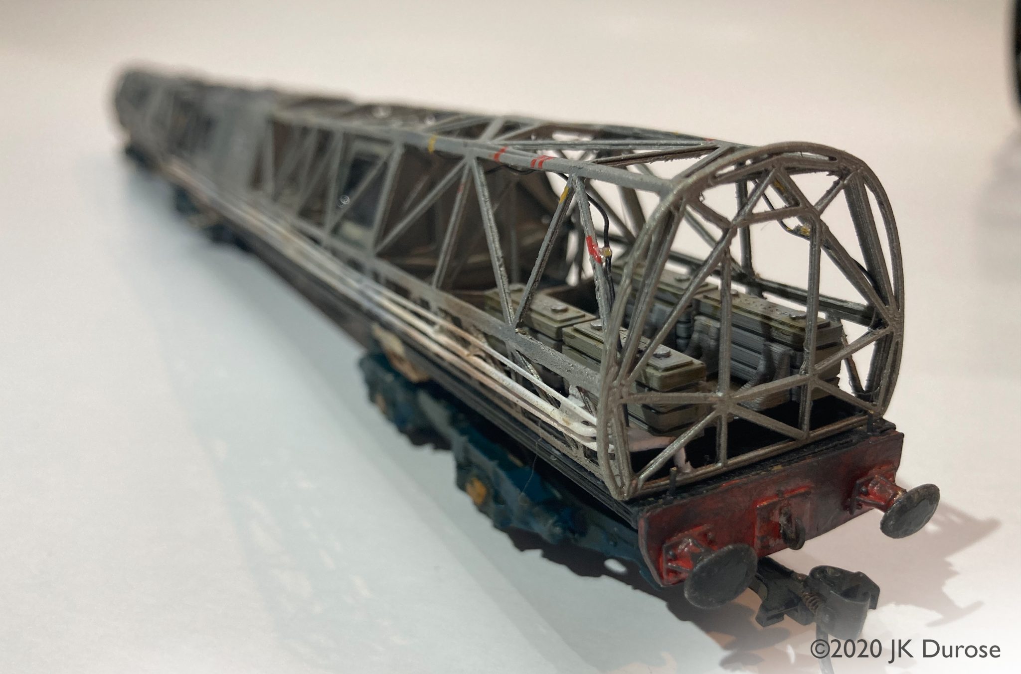
The completed model ready for it’s new owner.