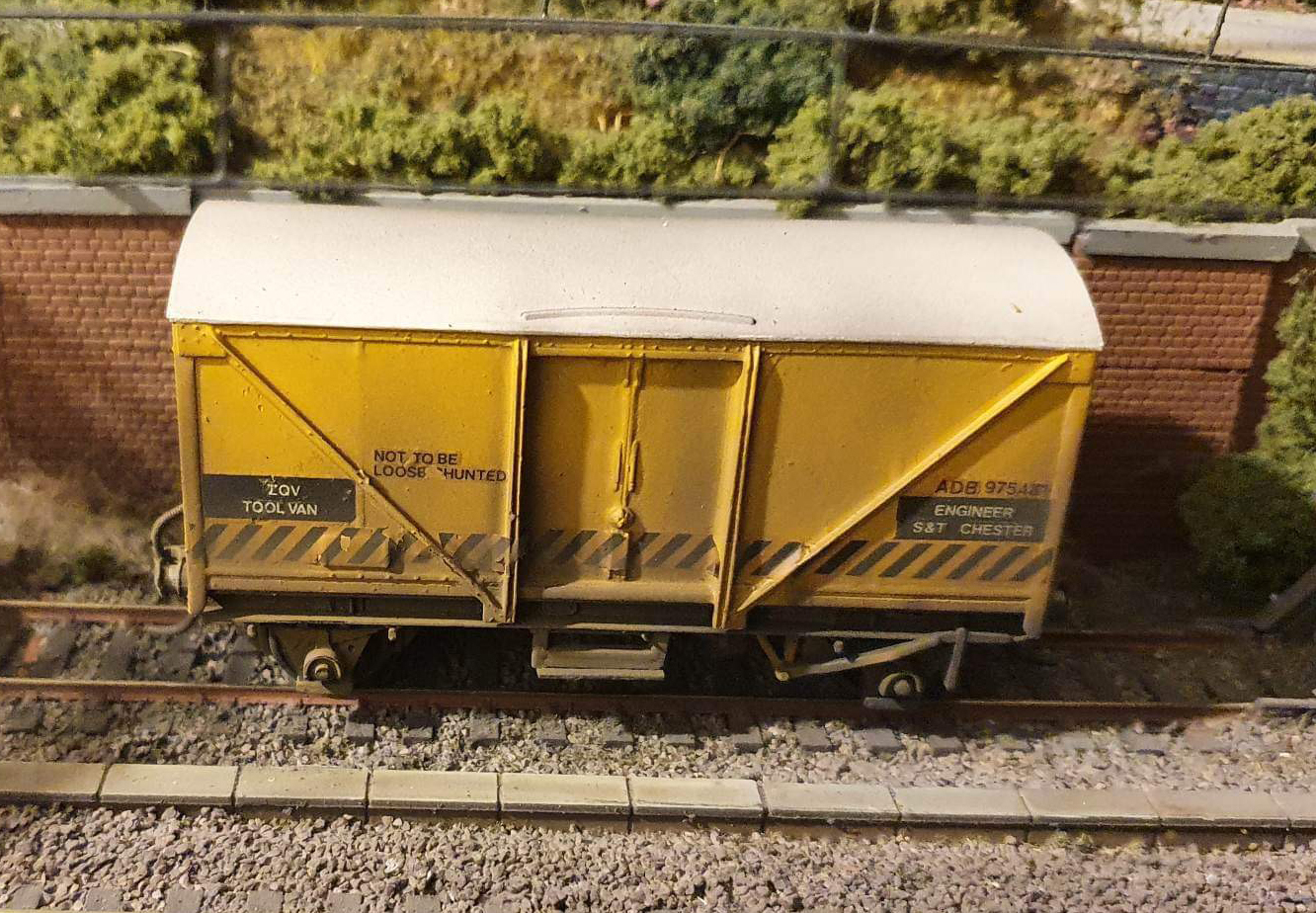

 Schools Tender Snowplough kit")
")
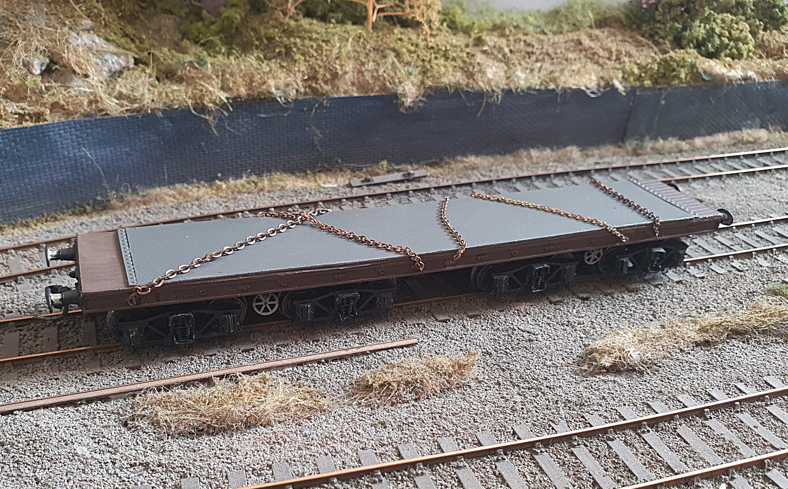
 Conflat D kit")


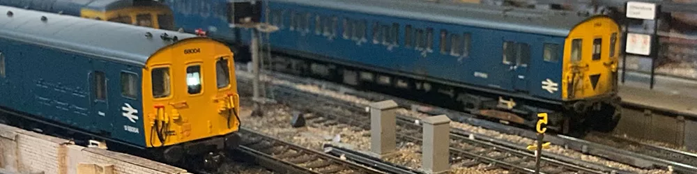
The RTC’s Tribometer set was put together in the early 1970s to help understand rail adhesion and develop ways to improve low friction.
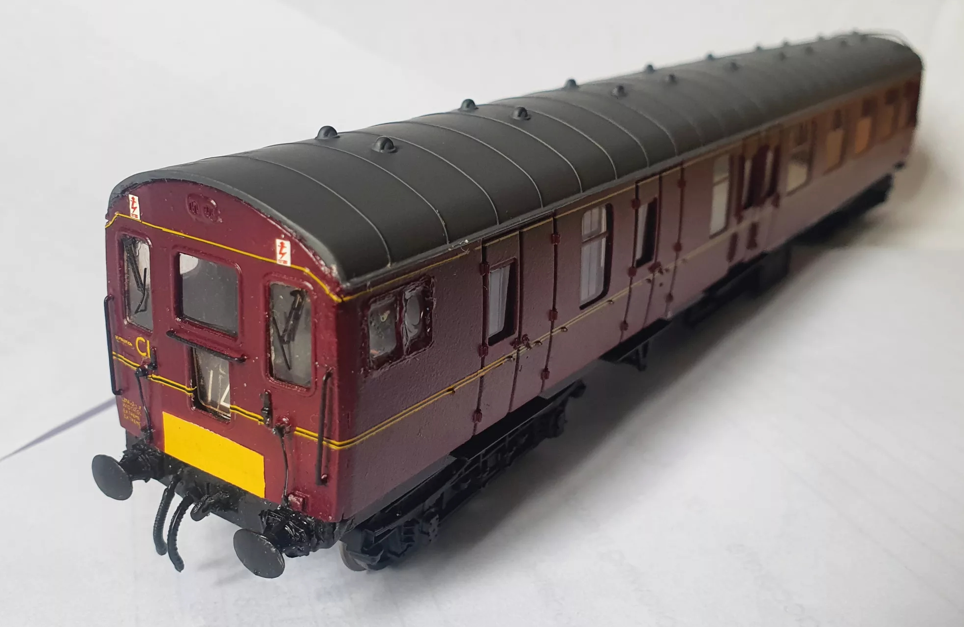
It has always been a popular item for B.R. Blue modellers to represent on layouts due to it being a short rake of 3 vehicles and it’s fairly widespread use around the network.
Bachmann, via the Modelzone outlet, produced a set some years ago including the Auto Trailer. Although the livery was striking, there were many inaccuracies in the body, of which the most noticeable was the lack of a driving cab end!
The imminent release of a 3D resin printed end and bulkhead from 12A is therefore a very welcome addition for RTC modellers.
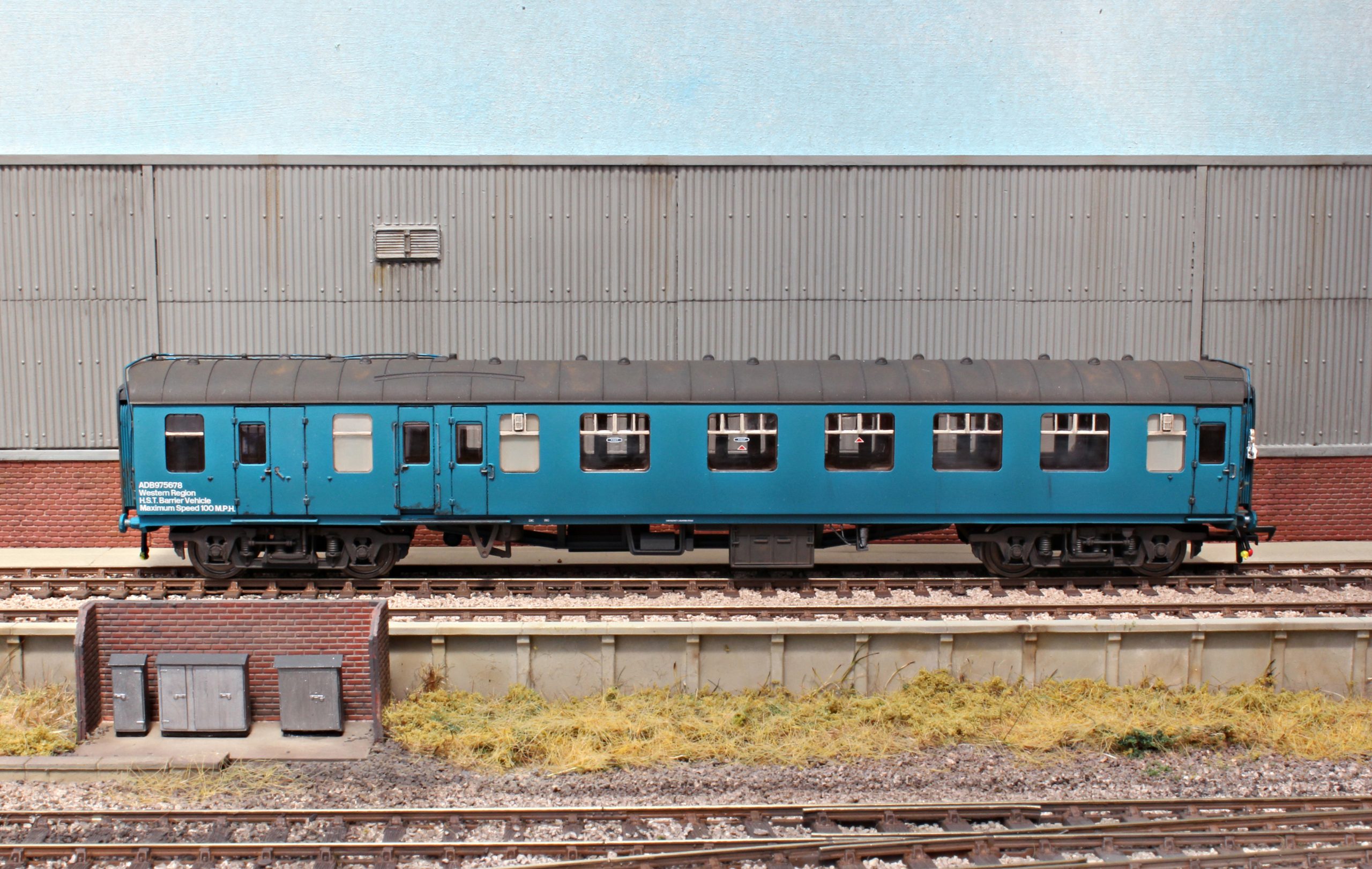
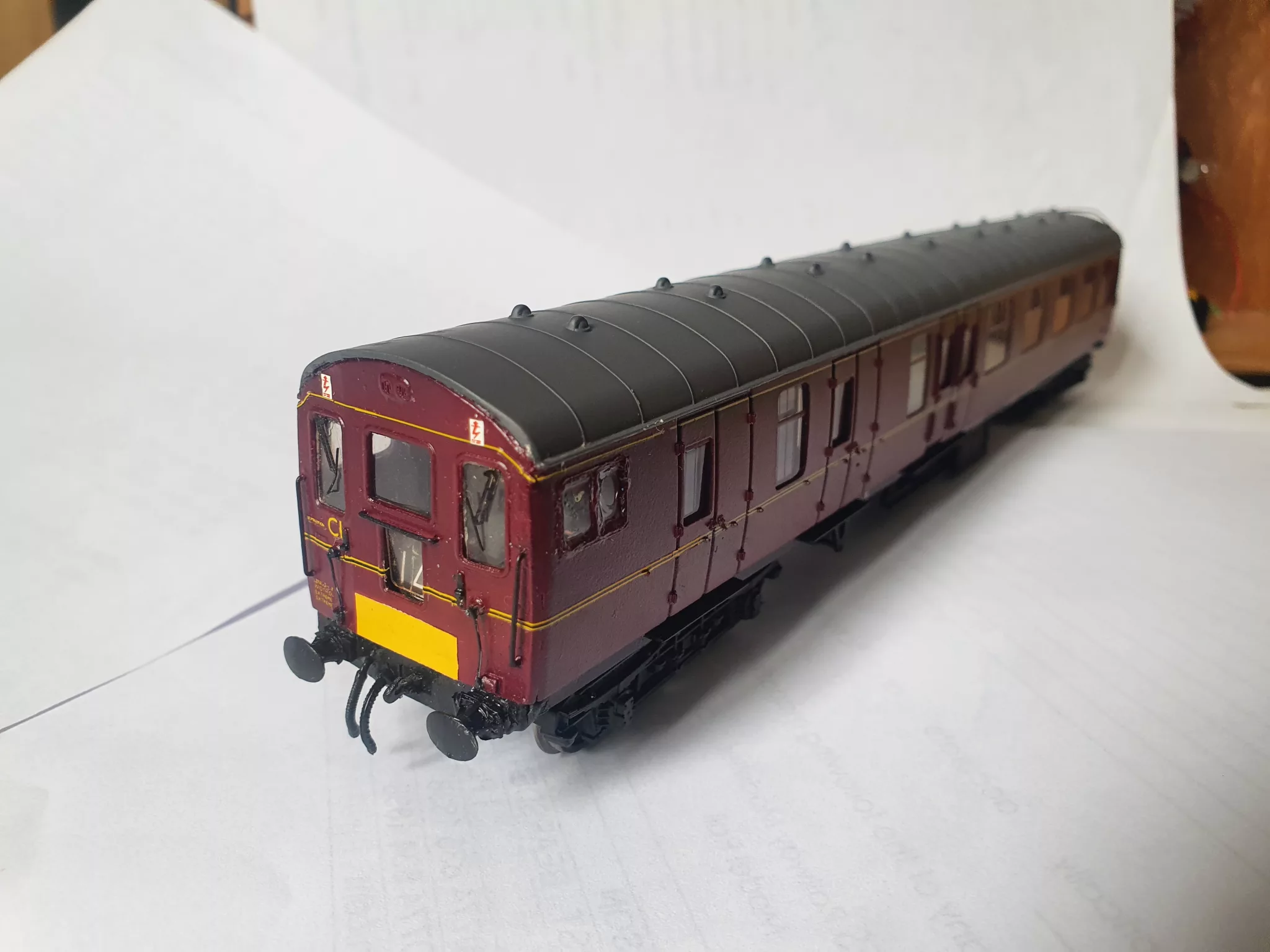
Below is a short, brief overview of the parts in the kit, how to fix them to an adapted Bachmann MK1 BSK coach, and what your completed model will look like.
The first thing to remember is that 3D resin prints are brittle, especially around the finer detail areas. It is best to sand this product rather the file it if you need to tweak the sizes to fit. If you are to use files avoid coarse ones as these will just damage and crack the product.
Note that this product is intended for converting a Bachmann Mk1 BSK coach. The Triang Hornby MK1, although similar in construction will not be quite the same measurements. Likewise, the Lima and Replica coaches will be unsuitable too.
Kit Contents
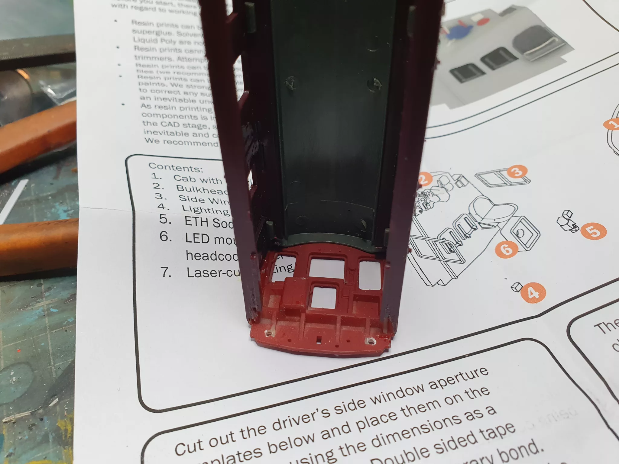
The kit is sold as a “scratchbuilding aid” and only requires a modest level of skill to complete. The following parts are included:
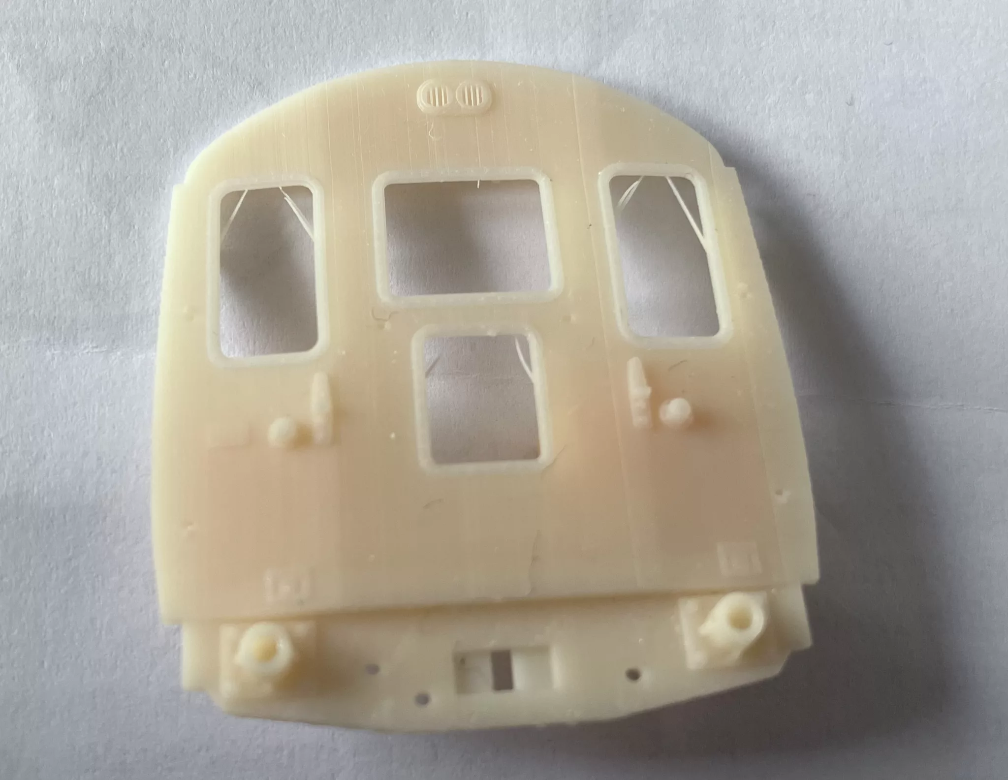
- 3D resin printed cab with detailed driver’s desk
- 3D resin printed rear bulkhead with detailed pipework and seats
- 3D resin printed destination blind box (with LED hole)
- 3D resin printed cable cups (tiny!)
- 3D resin printed ETH socket (optional dependent on era)
- Laser-cut glazing
- Laser-cut side window frame overlays
- Printed instructions and cutting templates

Preparation
Firstly, we need to dismantle the coach. Unscrew and Remove the bogies,then remove the 3 small screws that hold the bodyshell to the chassis.
Gently pull away the toilet filler pipes from the chassis ends and store all of them safely away. The roof should now unclip from the sides that pull out from the recess on the chassis. Note that these sides are ‘handed’, important to remember as you don’t want to be sawing off the wrong end of the coach! Remove the glazing, some Bachmann glazing is glued in better than others. Again notice the roof clips on the glazing and which go where, important for reassembly to ensure the windows go back in flush.
A point to mention before we progress is the bogie and roof details. When the coach was in maroon livery it ran on original B1 style bogies, only being changed to B4 type when it was put into the tribometer set.
The roof periscopes need to be removed (they simply pull out with fingers or grips). The small rectangular holes then need filling with a small slither of plasticard. Also remove the toilet filler hole at the ‘new’ cab end, fill and smooth. You will also need to remove the end plastic support on this end too to enable the end cab end to fit correctly. Remove with a knife/ scalpel and smooth to the profile of the inside of the coach roof. As always I spray my roofs with Humbrol matt Tank Grey. Once this is finished the roof is complete and can be put to one side for now.
Turning to the body sides the only modification needed is to cut out the driver’s side window. It will be easier at this stage whilst the sides are separate and flat (as the photo shows, I didn’t!). Luckily, a pair of templates are provided on the instruction sheet, which if cut correctly, will fit the window frame overlays perfectly. Clear tape or double-sided tape is ideal to fix it on the coach as you can still see through it when drilling/ filing. A good clean edge is important here so that the pre cut glazing will fit once the window frames are fixed on. I didn’t clean the edge as much as I should have which resulted in me having difficulty fixing the glazing later.
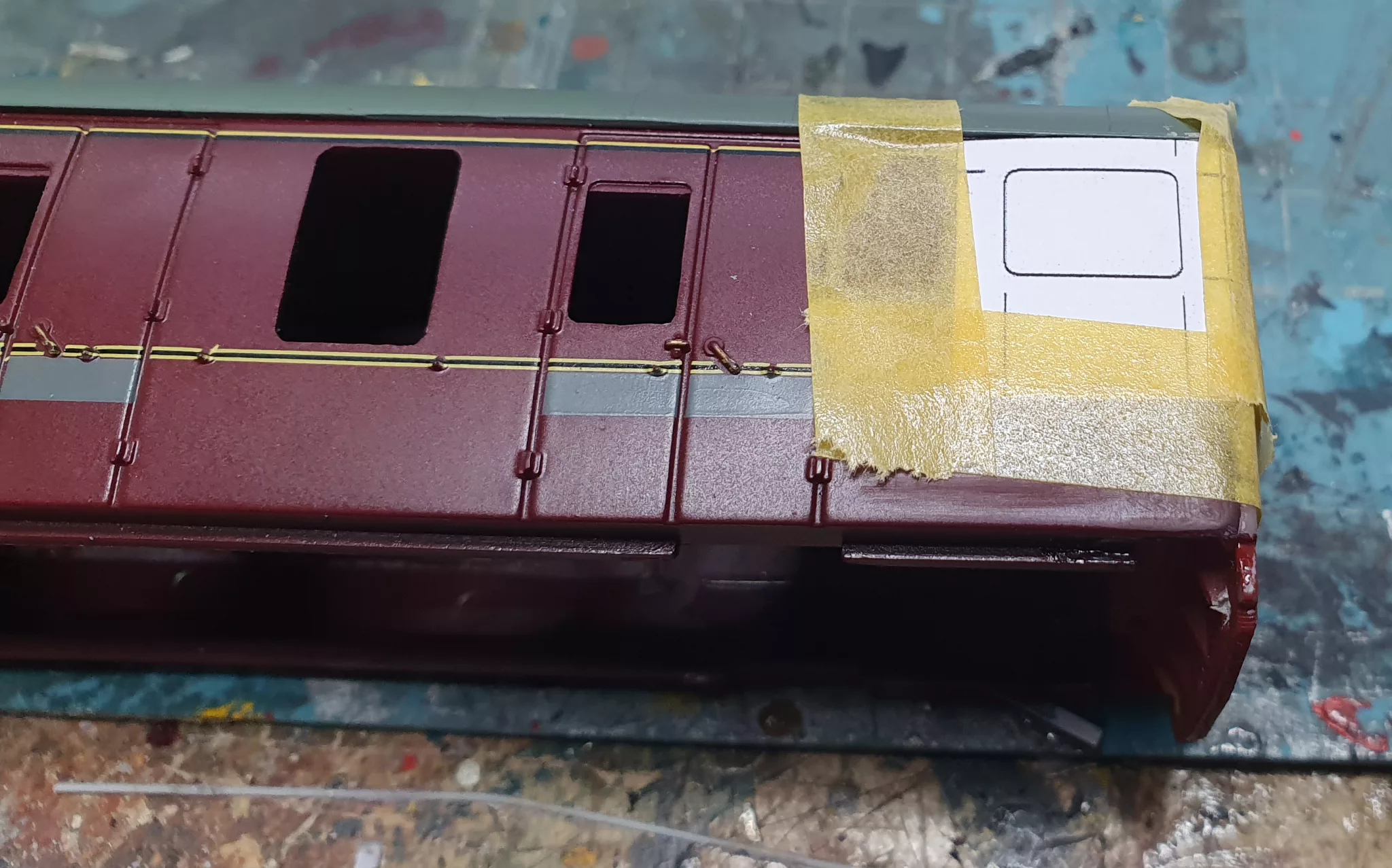
Once happy with the window cut outs fix the pre cut window frames to the bodyside. Again, accuracy is required, not only to get straight and level but also to cover the window cut out evenly. These are cut from Teslin plasticised paper, and can be fixed with liquid poly, Mek-Pak, PlasticWeld or similar only needing a small wipe around the edges to secure. Due to the finesses of the frames they won’t survive being taken off/ repositioned, hence that’s why there is a spare supplied!
On to the end then! Remembering to remove the correct end with a razor saw cut DIRECTLY behind the buffer beam as close as you can to the inner edge of the floor/end. The better the vertical cut the better the cab end will fit. Clean off any burrs with a fine file and offer the new cab end to the floor. An helpful tip here is reassemble the coach temporarily holding the sides and roof back in place with masking tape whilst you get a good fit on the cab end/sides/roof profile.
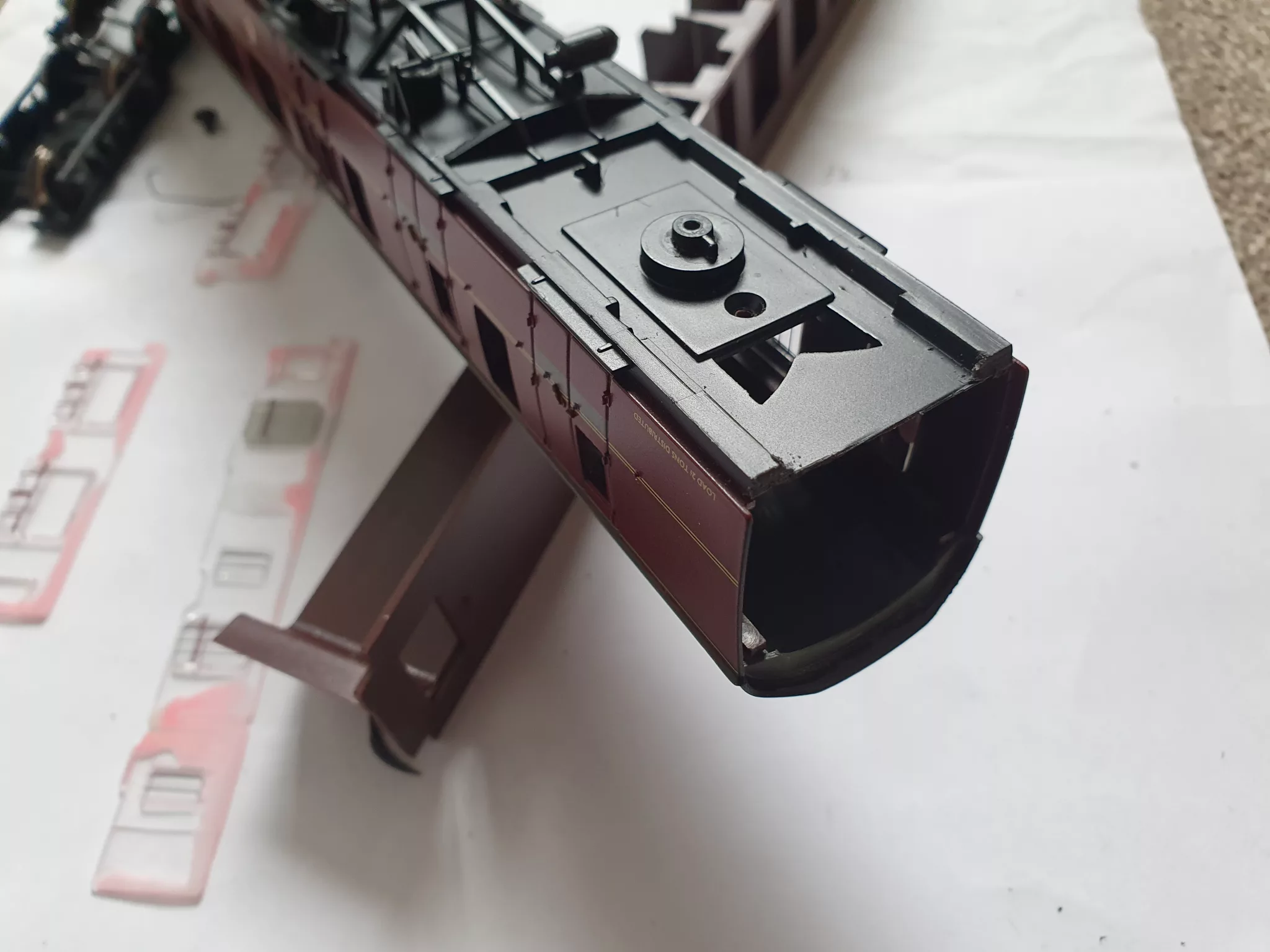
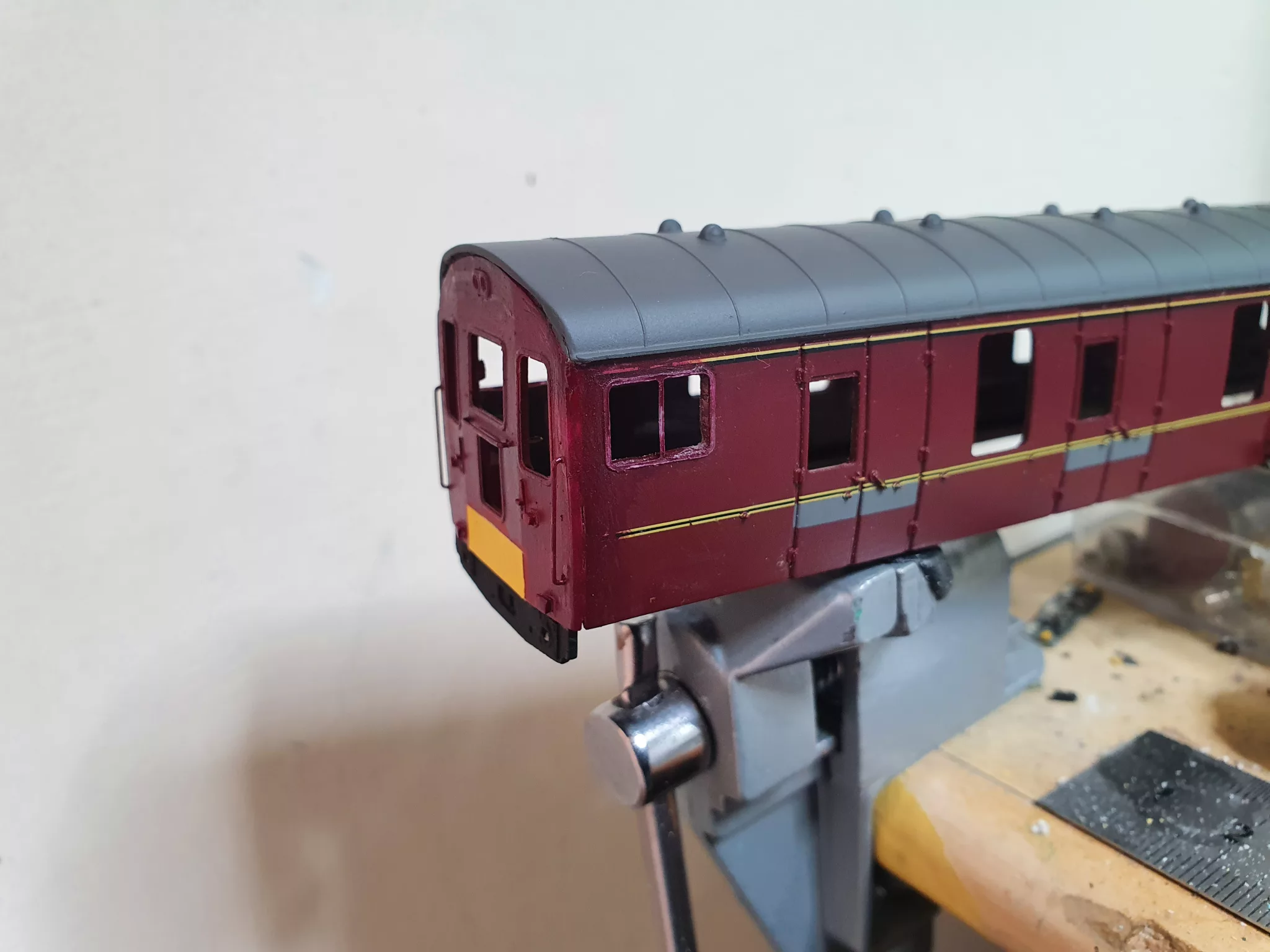
The new cab end should fit as the original end did just on the edge of the side. Once you are happy with the fit glue using cyanoacrylate along the bottom edge. Depending on how you are going to resemble the coach, your modelling ability and painting techniques will depend on if you attach the cab side to the front or not. Both myself and Shane Wilton have built this cab end as a test and we have both used differing methods so the preferred method here is left to the modeller.
Secure the inner underside of the buffer beam/floor ideally with a bead of filler or glue. Depending on your build method now is the time to fill the small edge where the cantrail corners of the new cab end meet the sides. Also to note is the fit of the roof to the new cab end. Due to the nature of the 3D resin part there may be some slight tolerances so some slight filing and sanding may be needed to obtain a fit satisfactory to you
(Kim’s note – the curvature of the roof profile has been tweaked 0.25mm since Mark and Shane built these test models).
Once you are happy overall, you may need to drill out the handrail holes using a 0.4mm drill bit in a pin vice. There are holes there, but these may need opening ever so slightly. Remember resin is brittle! Use a smaller drill and work upwards in size, likewise with the buffer holes. I used too bigger drill and resulted in cracking the buffer shank! It is advisable to use the buffers off the coach end you have sawn off earlier!
(Kim’s note – the holes in the buffer shanks now extend through the rear of the bufferbeam. This is an amendment made after receiving feedback from Mark.
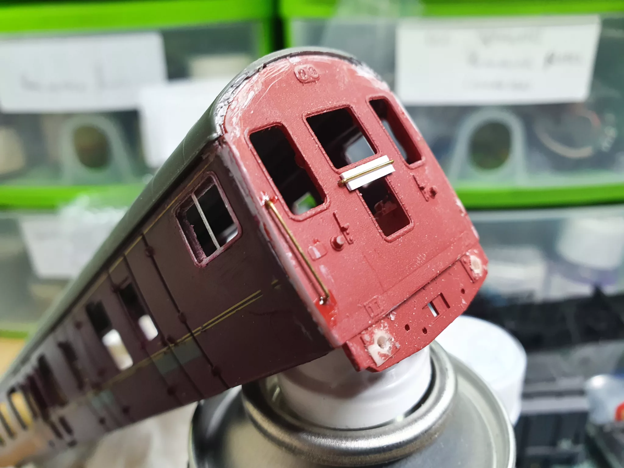
Fit handrails and the small electrical boxes (please note the change in position of these throughout the coach’s history). If in doubt refer to the instructions and photographs of the coach from your chosen period.
At this stage it is time for painting/spraying. As this article is not about painting or spraying I will leave this part for the builder to decide on their options. The shade of yellow did change over the coach’s history. It is advised that white primer is used for the end as a base for the yellow. Any good quality primer can be used on the 3D printed end.
Whilst the builder’s preferred painting technique is underway we turn our attention to the cab bulkhead part. The instructions include a handy painting guide. Once dry, fit a seated driver figure and accompanying standing crew if required. Cut back the Bachmann interior to the first door line and attach the bulkhead to the end. Remember to ensure the floor bottom edge is in line with the base of the interior remembering to allow for the side cut outs on the bottom edge.
If you have decided to illuminate the headcode box now is the time to fit the LED to the backbox , and to fit a headcode of choice. I recommend the Heljan ones that were supplied with their models and may still be available as spares?
Glazing
The pre-cut glazing should be handled carefully. The panes are held on to the backer with small nicks that ideally need to be cut with a sharp scalpel to release them. To fix it I recommend Humbrol Clearcote, Glue and Glaze or something similar. Avoid any sort of superglue as this will turn it white and frosted.
The cab front sections will fit into the recesses in the window apertures fixing with a few dabs of your preferred fixative in the corners. With clear cote it will run along the edges creating a bead around the edge and sealing the piece in place. The headcode panel piece can be treated similarly.If you have decided to illuminate the headcode box it may be an idea to paint the inside of this cab area matt black to help eliminate light bleed. The rest of the cab area should be painted in the same colour as the bulkhead head earlier. It is advisable to paint this before adding the glazing.
The side windows may be a little trickier, depending on your build method. If you still have two flat sides to fit then depending on how accurate your window cut out was the glazing piece should fit straight in! If you have decided to glue the sides/ ends to the chassis like I did then a bit of care is needed to glaze the side windows as they are not as accessible this way.
Finishing and detailing
Buffer beam detailing can now be added, working from prototype photographs. There were a few changes over the years. Holes are provided for pipework and a screw coupling hook. Buffer beam pipework can be made from various materials or sourced from model part manufacturers. Tip – if you know any bass guitar players, old wound strings make excellent vacuum and air pipes. Etched windscreen wipers (not supplied) can be added if required. Remember the two communication wires that come from the two round sections on the front to the lower boxes. 3A Fuse wire is recommended for this.
Re-assembly
We now turn our attention to reassembly.
Refit the original side glazing as there is no change to these, unless you have to paint the top window surrounds to match your livery. Glue and glaze is ideal for refixing this. The interior can then be placed in and the roof clipped back into place .There may be a need to remove a little of the end clip on the roof depending on your accuracy when building the end.
Replace the screws to the underside of the coach ( please note the front one nearest the cab end may need a small drill putting through as again depending on your accuracy of the bulkhead placing the screw hole may need opening out again.
Refit the bogies, checking the clearance at the cab end if using a coupling. If required sand the lower part of the buffer beam until clearance is obtained.
Sit back and admire your work and place the model into use.