

 Schools Tender Snowplough kit")
")
 Conflat D kit")


It’s only taken 26 years
Many many years ago, around 1997, myself, Richard and Mark were involved in a local model railway club and were exhibiting a BR(S) layout on the exhibition circuit. As many of the membership were of the steam generation we had a broad modelling period of post-nationalisation 1948 to 1968. At this time, myself and Mark were often discussing the possibility of building a model of either the 2-PEP or 4-PEP EMU.
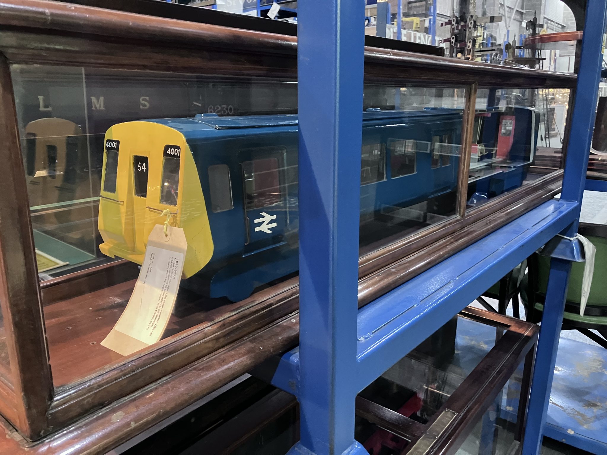
Constantly taunted by the BR York wooden mockup in the National Railway Museum, we never gave it much thought beyond “who’s brave enough to tackle the MTK kit?” and “it’s out of period anyway”. Over the years that passed since, the desire to build one never passed but as there has never been a suitable base from which to start, it never happened.
The Prototype
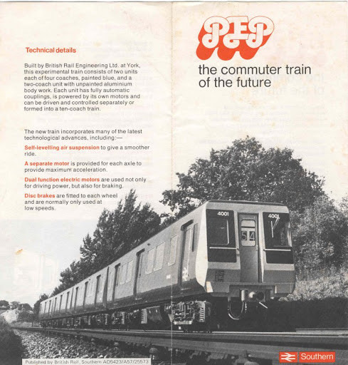
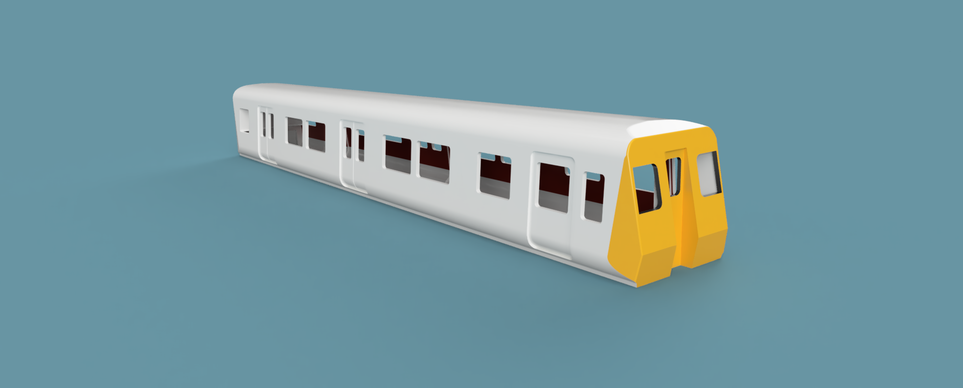
The real PEPs were built in 1971 at BREL York and were the forerunners of second generation EMU classes 313, 314, 315, 507 and 508. Three units were built, 2 four car units known as 4-PEP (TOPS class 445) and a solitary 2 car unit known as 2-PEP (TOPS class 446). They were the first British Rail designed units to feature sliding doors rather than the traditional “slam door” units which featured heavily on the Southern Region commuter network.
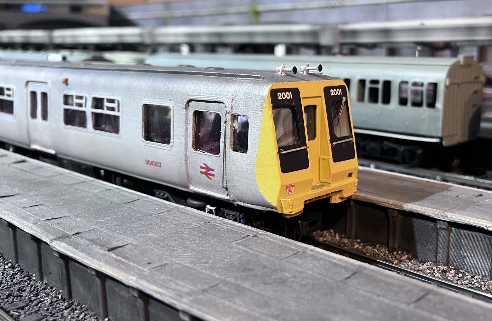
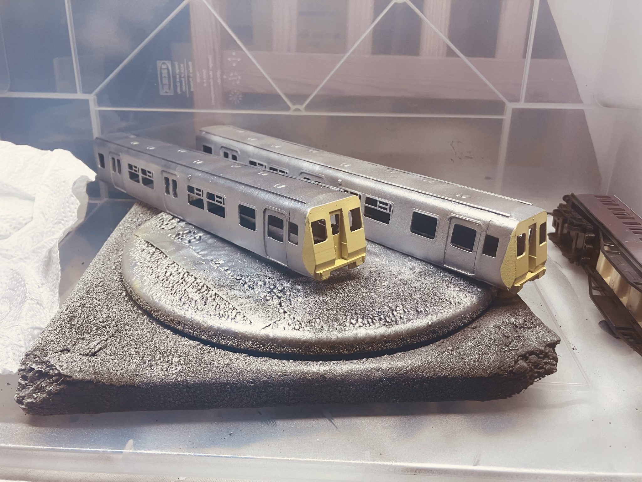
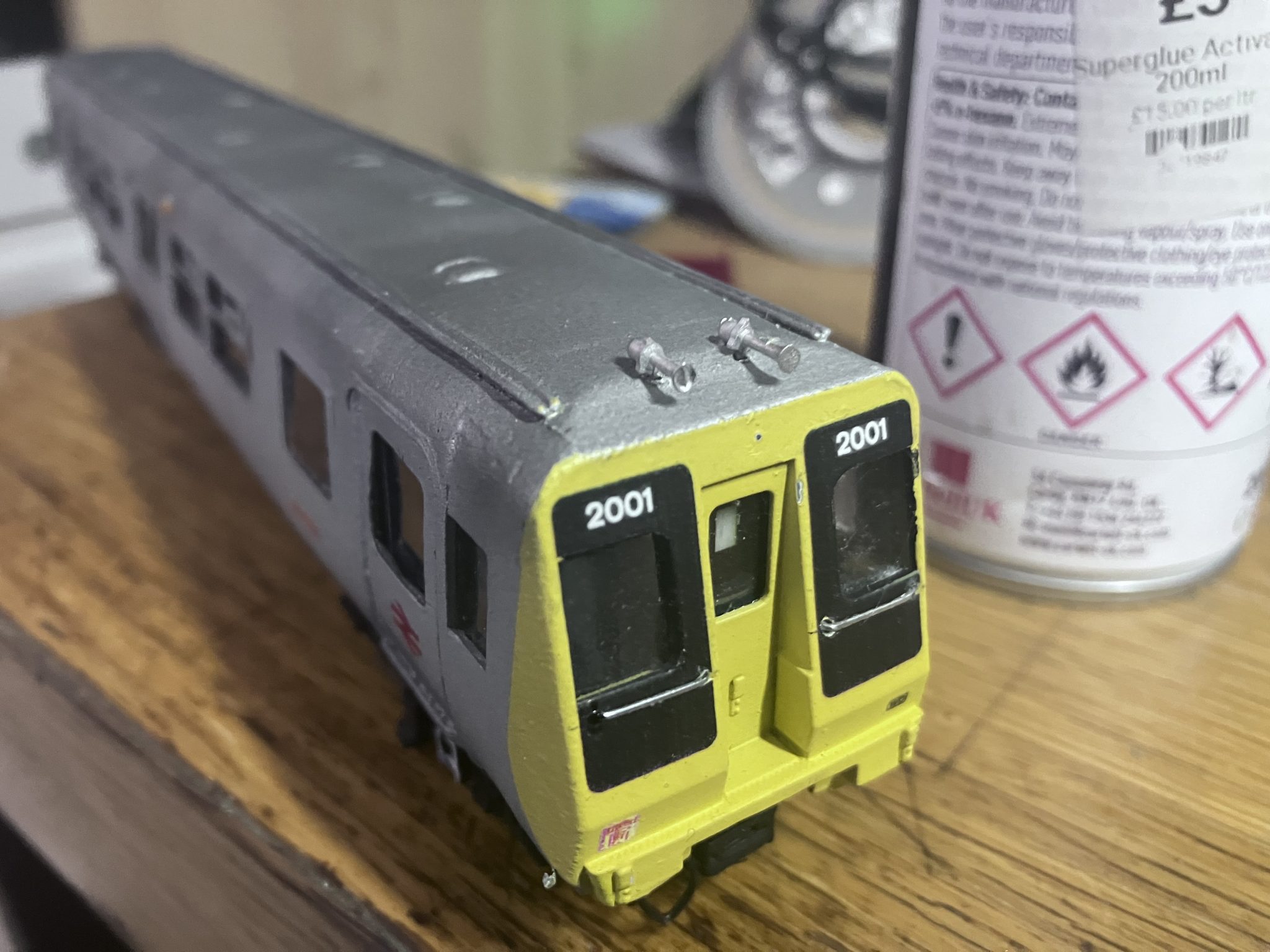
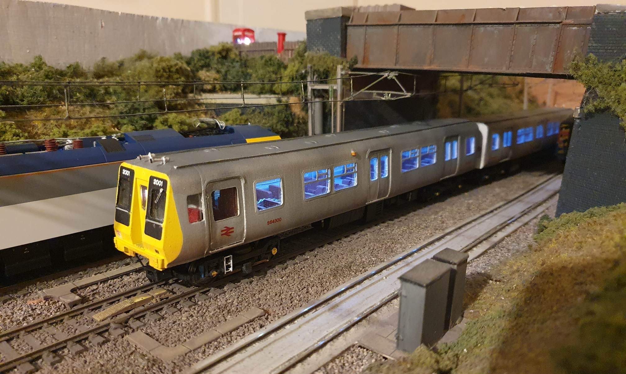
The smaller unit, 2-PEP No. 2001, was outshopped in unpainted aluminium livery, whereas its larger sisters, 4-PEPs 4001 and 4002 were both painted plain rail blue. All carried full yellow ends and black window surrounds.
None of the units had toilets onboard, and all featured a spacious uncluttered open cabin space with 2×2 bus style seating in tan vinyl, with grey interiors and glazed red partitions either side of the doors. The coupling system was unique for the network, with the outer ends of each unit carrying a Scharfenberg coupling. It is widely believed that special barrier vehicles were used to move the vehicles around the network when not on the 3rd rail network. However, a chance conversation between myself and someone who worked on the units in those early testing days revealed that nothing so elaborate had been constructed. Instead, a simple adapter was fashioned from steel at Eastleigh to form a bridge beween a standard drawbar hook and the Scharfenberg. Incredible, but true.
Thoughts turn towards a model
In 2016, I went to a digital printing expo in Amsterdam and among the exhibits were several types of 3D printers from several vendors. Despite no longer being an active modeller at the point, I could see the creative potential that lay within. In 2020 things took a bit of a positive turn during desperate times. During the Covid-19 pandemic lockdown I bought a cheap Chinese Ender 3 Pro FDM 3D printer. Armed with this, some rudamentory 3D CAD knowledge, works drawings and over 120 photographs, tentative moves were made to first create PEP in 3D, and then work out how to build it.
During this time I had drawn and built two complete 2-car items for Mark, in the form of both flavours of POP Train, the prototype tilting train that formed the testbed for APT-E. The second one was extremely complicated, and the thought of building “a basic tube with windows” after that was easy. I was so very wrong.
Mark turned up at my house one Saturday with a gift. It was a Dapol Class 150/2 Sprinter and a box of Lima 156 bogies. “The Sprinter is yours, the bogie frames are mine. Its for a 2-PEP each, mine will be unpowered”, and with that he drove off in his van. As he’d just sold me a Bachmann 4-CEP at “mate’s rates” I was in no position to argue and to be honest, the uniqueness of the build excited me. What followed was around three months of resource gathering. Book buying, photo downloading, and tentative drawing of 2D profiles.
It is very hard to document and describe the process of 3D CAD building. Everyone I know tackles it differently but I can give a brief outline of how I tackle it. I always start off with a quality drawing. If a 4mm scale one is available, great, if not I can scan it and scale it in software. I use these drawings a “canvas” on which to draw 2D profiles. I always draw 1:1 for 4mm scale. It’s why none of my drawings are suitable for 2mm scale or N-gauge. The printed models would be too thin and would collapse under their own weight when printing. Where possible I use proprietary components. Lima made lovely bogie frames for the 156, whereas Dapol‘s were crude in comparison on the 150/2. As I was building the unpowered “dummy” unit for Mark first, the Dapol unit was put aside and the Lima 156 bogies earmarked. Apart from that, with the excpetion of small detailing components, that’s pretty much where it ends and everything else had to be drawn from scratch.
Several iterations of the design followed and the project ground to a halt for “thinking time”. I just was not happy with the lack of finesse of FDM printing, even though I had now got the Ender 3 Pro beautifully dialled-in. Everything changed again when a friend and fellow modeller offered me his far more refined Elegoo Mars 2 Pro resin printer. The floodgates opened and it seemed for a while anything was possible. However, as anyone who’s worked with resin will tell you, it’s horrible. Just horrible. It is a wet process very susceptible to shrinkage and warping. Building straight coaches with thin walls just isn’t do-able, so I started to think about combining both processes and traditional modelling methods to achieve the result and PEP is the first fruits of working this way.
They say a picture paints a thousand words, so I will go through the build using photos and CAD renders to explain the process.
Enjoy!

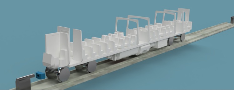

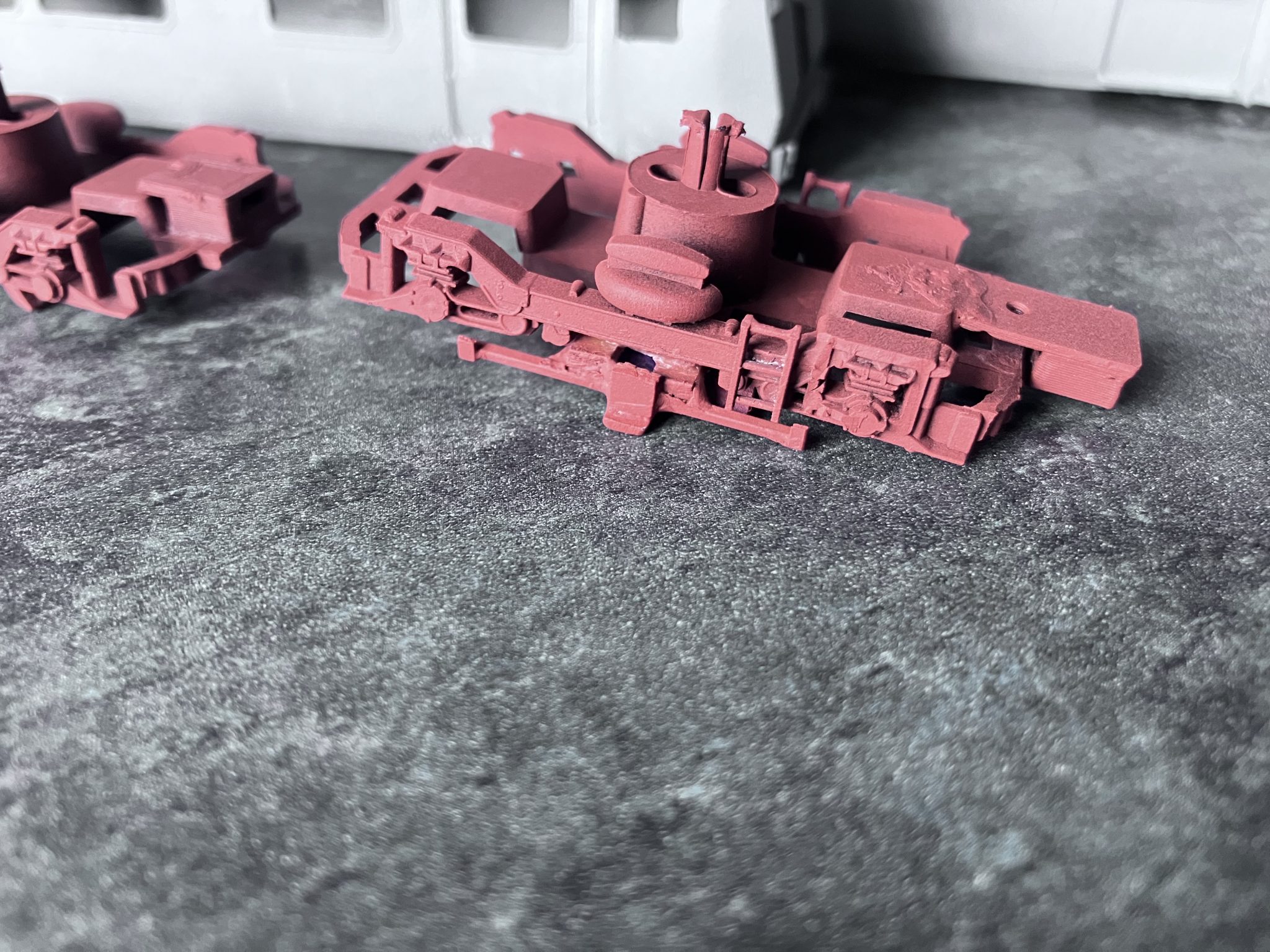
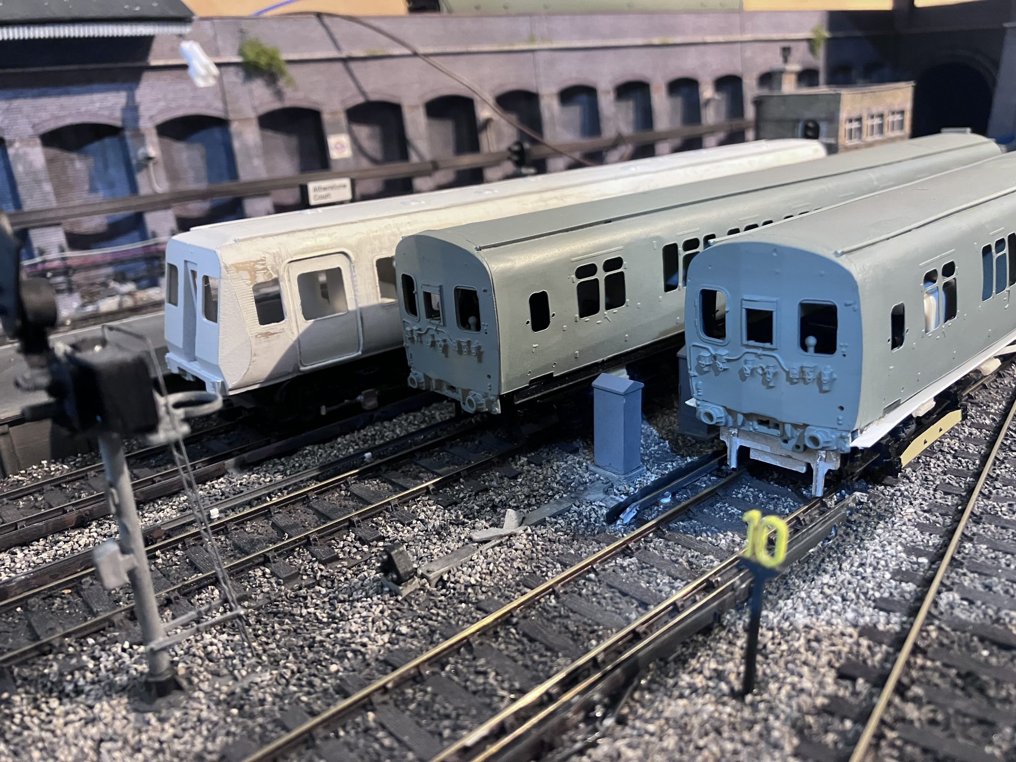
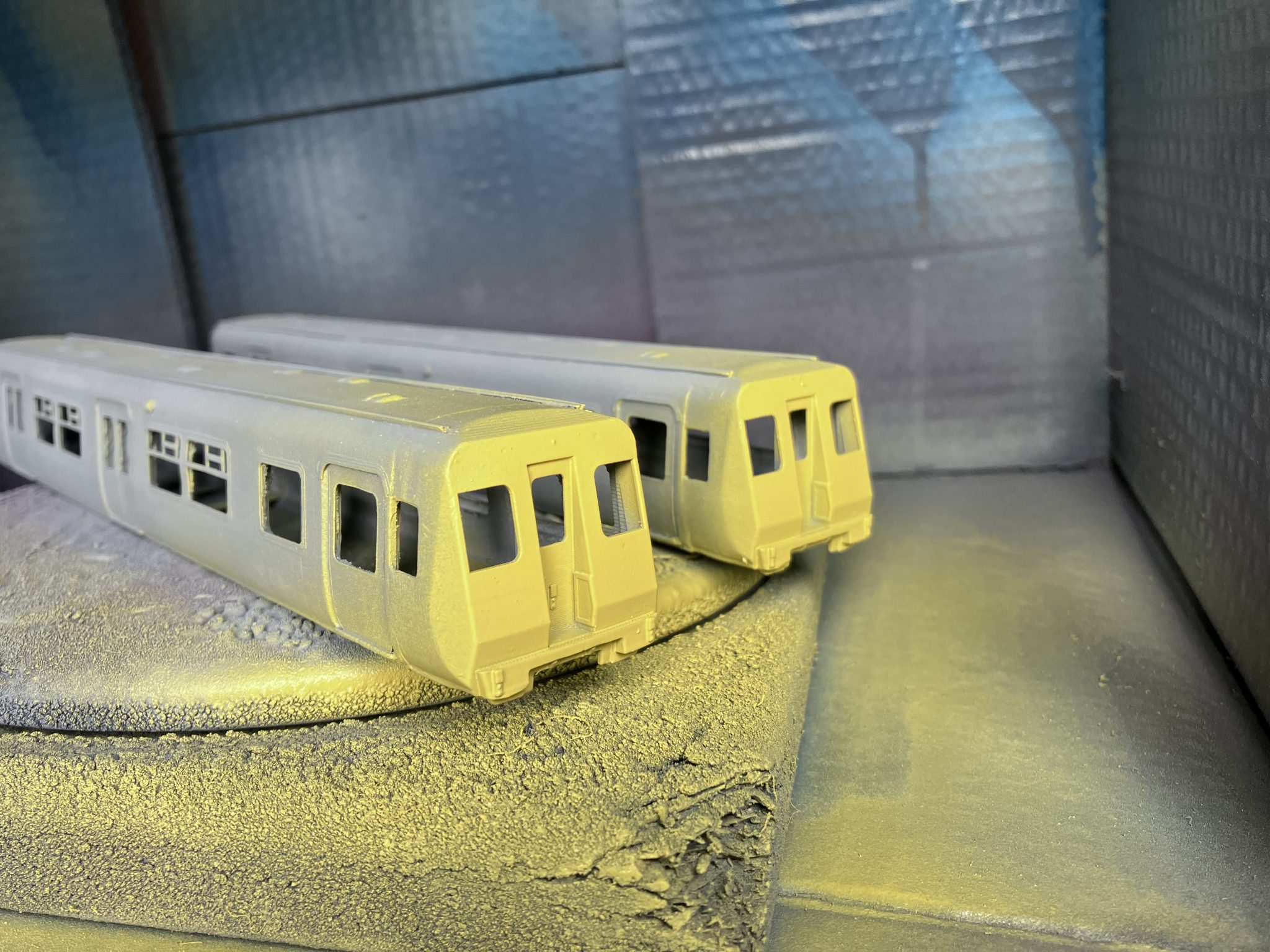
A total of 4 prototype models were printed. 3 of which still sit on my shelf in the modelling room. I finally settled on an FDM printed shell and chassis, with resin printed ends and underframe details. The reason being is that FDM is great for achieving integrity and strength. Resin is great for detail and finesse but terrible for strength and accuracy. Combining the two processes brings together the best of both worlds.
Video showing a timelapse on the Ender 3 Pro printing a bodyshell section from PLA+ material.
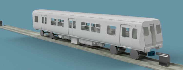
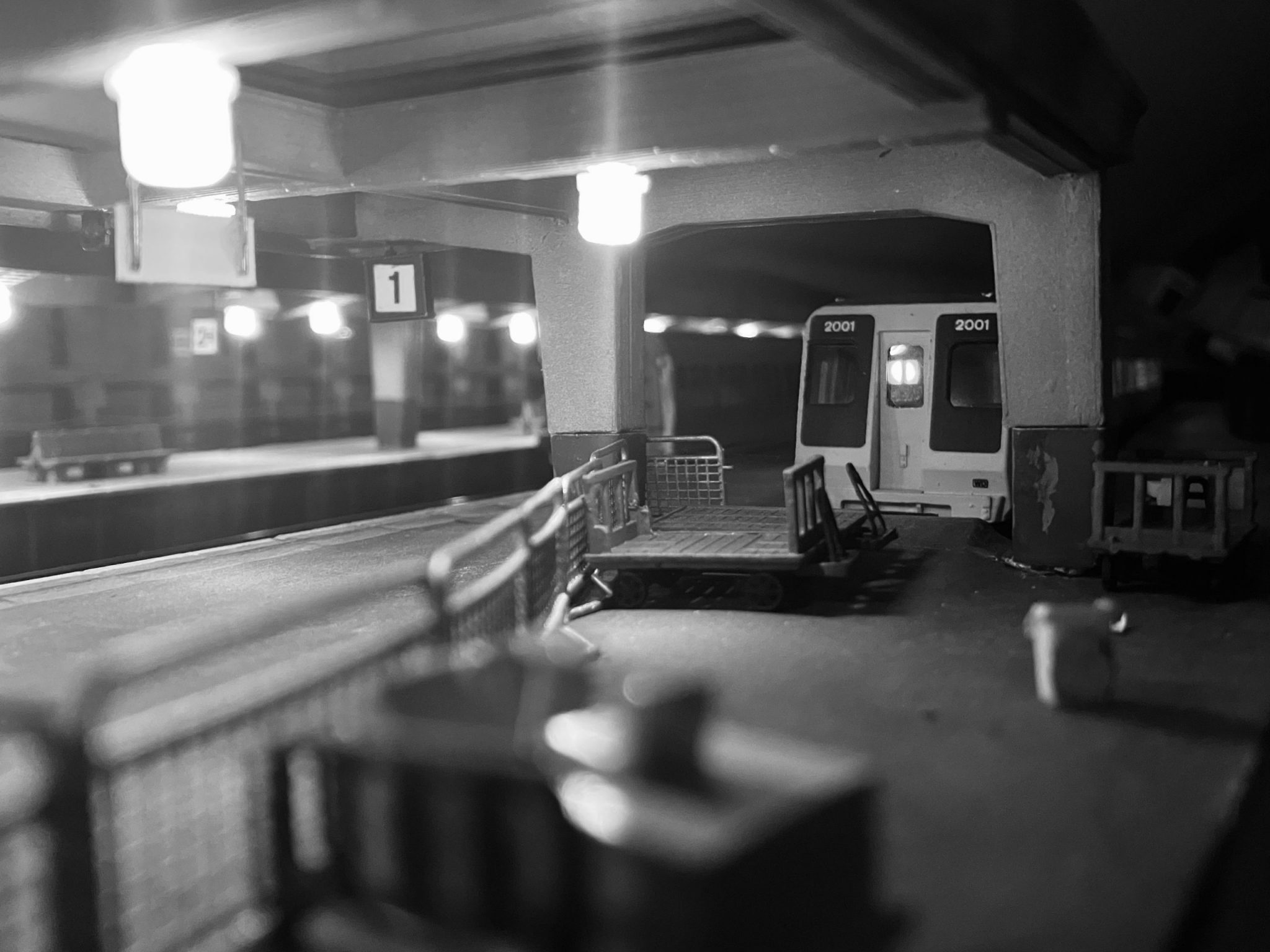
The initial build was an unpowered dummy built for Mark Pearson’s “Welby Lane” RTC layout. The unit features 8 pin DCC sockets, bidirectional lighting in the headcode boxes and flourescent cabin lighting using LED strip. The beauty of having a DCC decoder in each car is that one avoids the need for cross-vehicle wiring and/ or clumsy plug and socket connections. Motor connection wires are wired in and tucked away out of sight, for the inevitable day when Mark decides to motorise it with a Tenshodo Spud.
The plethora of underframe boxes are designed with a central channel which cannot be seen. This allows the DCC decoder harnesses to be fed to the socket without removing the body. Internal wiring for the lights and pickups is carried along the floor in the aisle, painted grey so it cannot be seen from the outside.
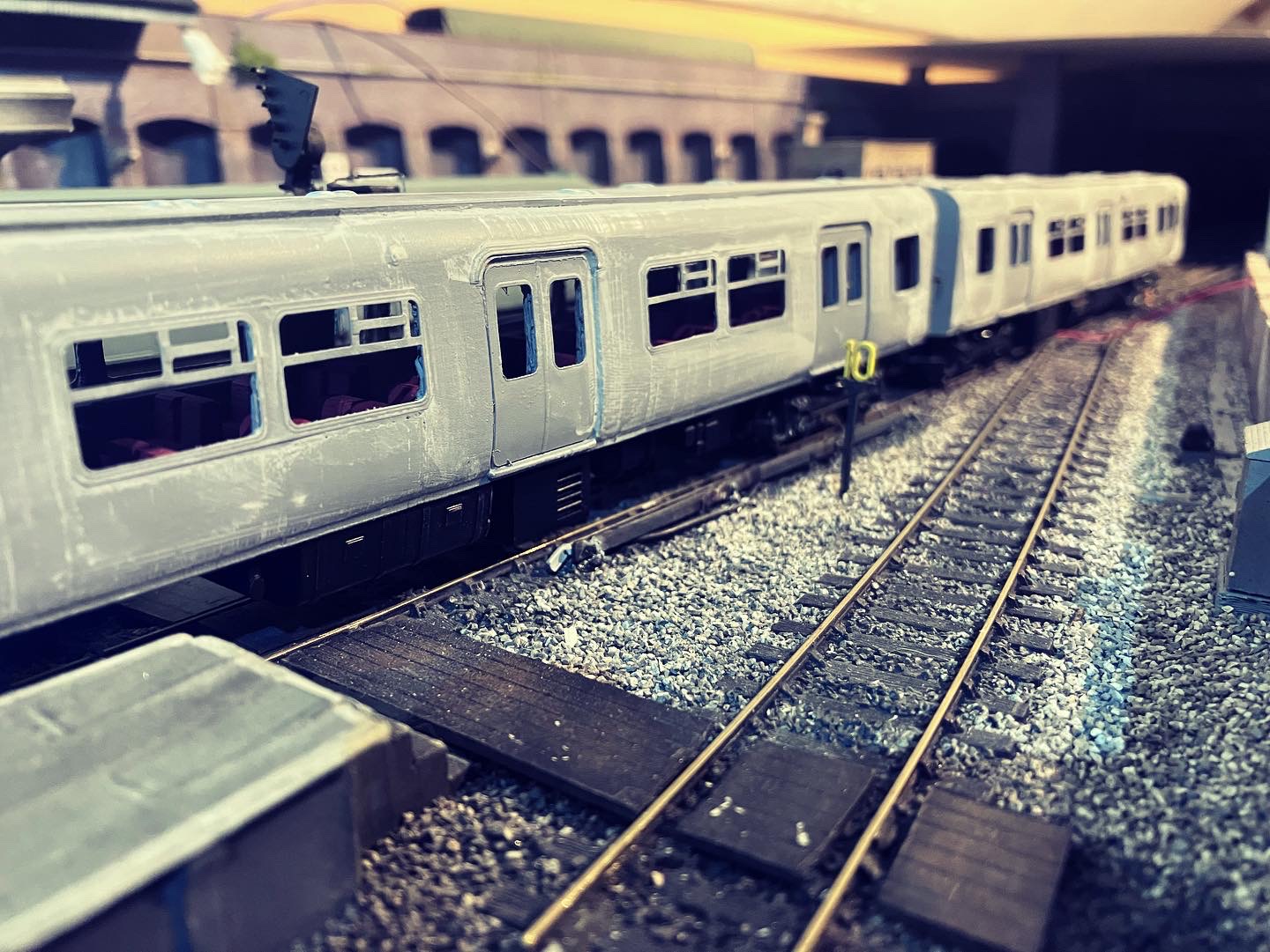
With the unit printed, a revealing coat of fille primer was applied which shows up all those nasty layer lines from the FDM printing process. Getting rid of those is actually very easy. There is much written about “print smoothing”, “acetone vapour” and all manner of chemical horrors designed to part us with money and life expectancy. As modellers we paint everything, so finish isnt that important “off the bat”. I use Valejo Liquid putty (the expensive method) or Revel Plasto. Plasto can be mixed with water to make a slurry. I mix this to the consistency of milk (skimmed, not full fat) and just wallop it on with an old broad flatty paint brush. Leave it 48 hours to dry and then give everything a rub down with 1500grit wet and dry used wet. The result is a lovely smooth bodyshell.


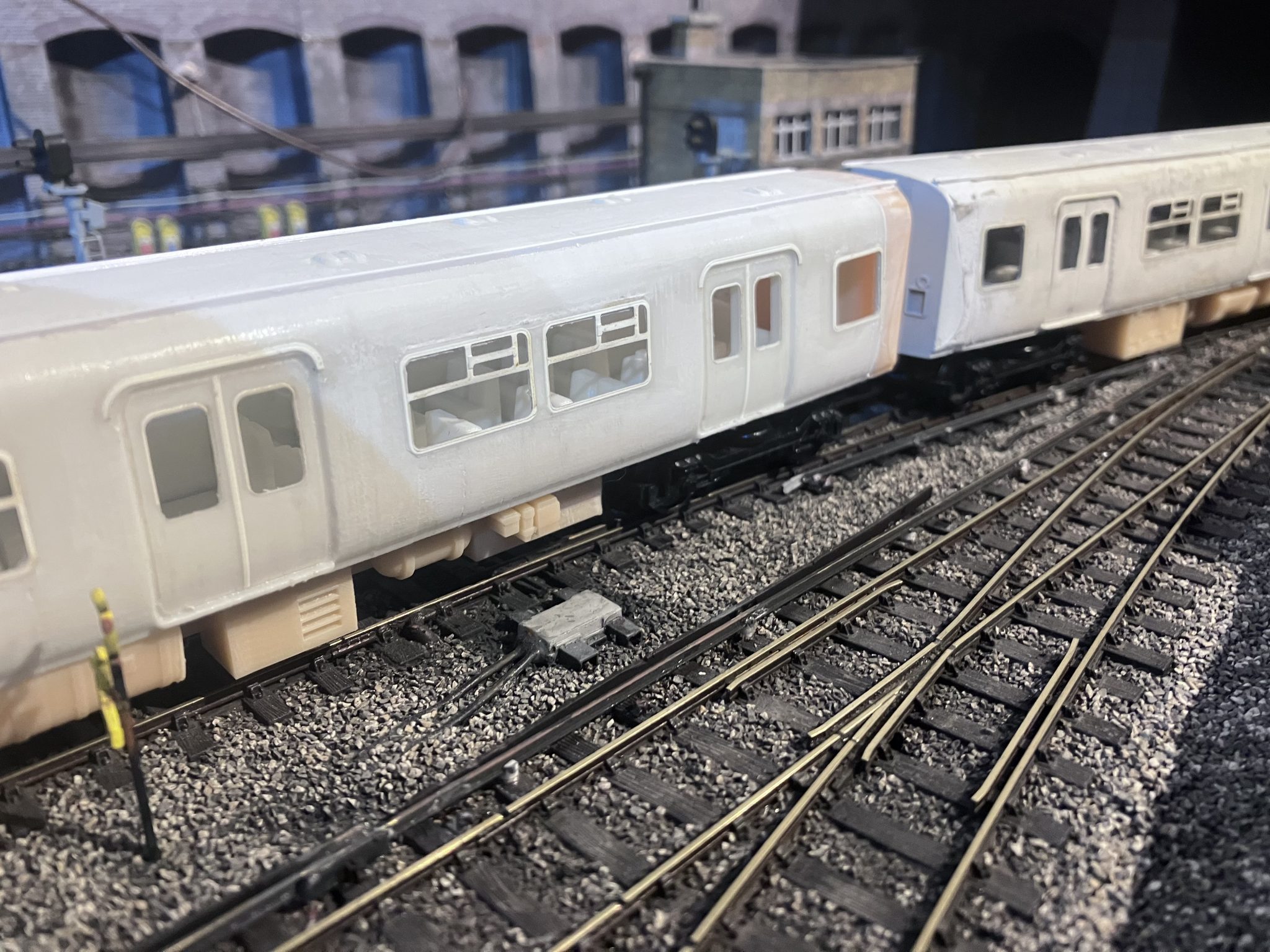
The body and chassis is tethered using six self-tapping M2 screws, a la Bachmann. Attempts were made for a mechanical clip but simple is always best.

Window frames are laser-cut from Teslin plasticised paper and applied with PlasticWeld liquid adhesive. Who knew that paper could be glued to cornstarch with plastic cement? Me neither!
I hope you have enjoyed this brief insight in to how PEP was built. I’m very pleased with the result as it’s shown me what I can achieve with two essentially entry level 3D printers. Another 2-PEP and both 4-PEPs will follow for Atherstone Court.
Thoughts, criticism and comments are always welcome!
would like to try and do one for n scale.