
 Schools Tender Snowplough kit")
")
 Conflat D kit")


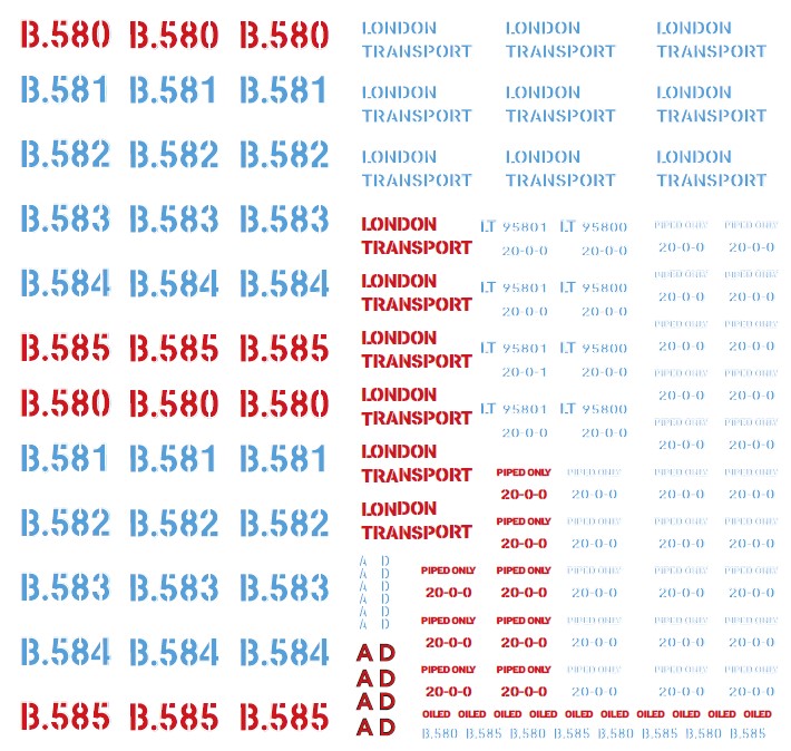
The humble BR 20 Ton brake van was a common sight on the BR network from the early 1950s up until the 1980s. In 1962, London Transport, still utilising steam-hauled freight on surface lines, placed an order for six BR Standard 20T brake vans, which were built at Ashford Works. These were numbered B580 to B585.
With the demise of steam on the LT network, the need for brake vans decreased and the numbers reduced. Some were held back for special duties and exhibition work, and four of the 20T type were converted in to match wagons.
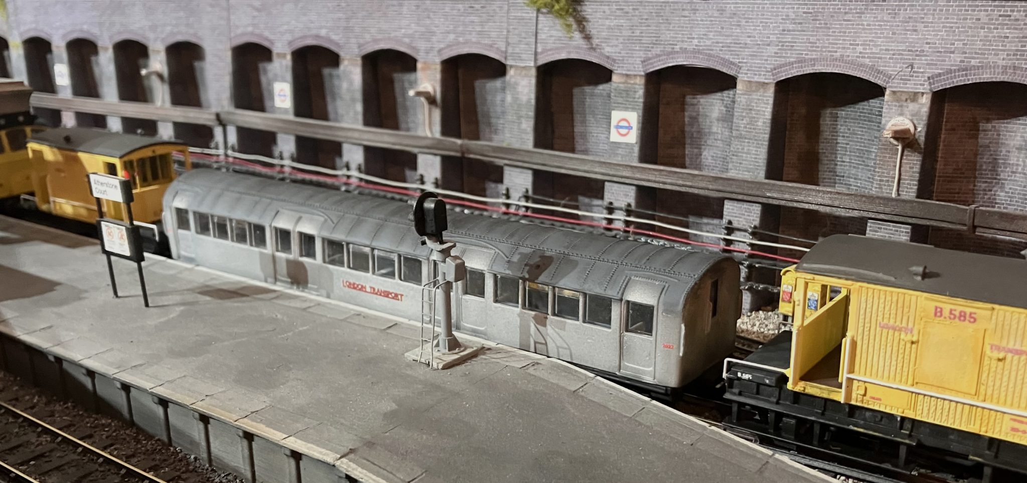
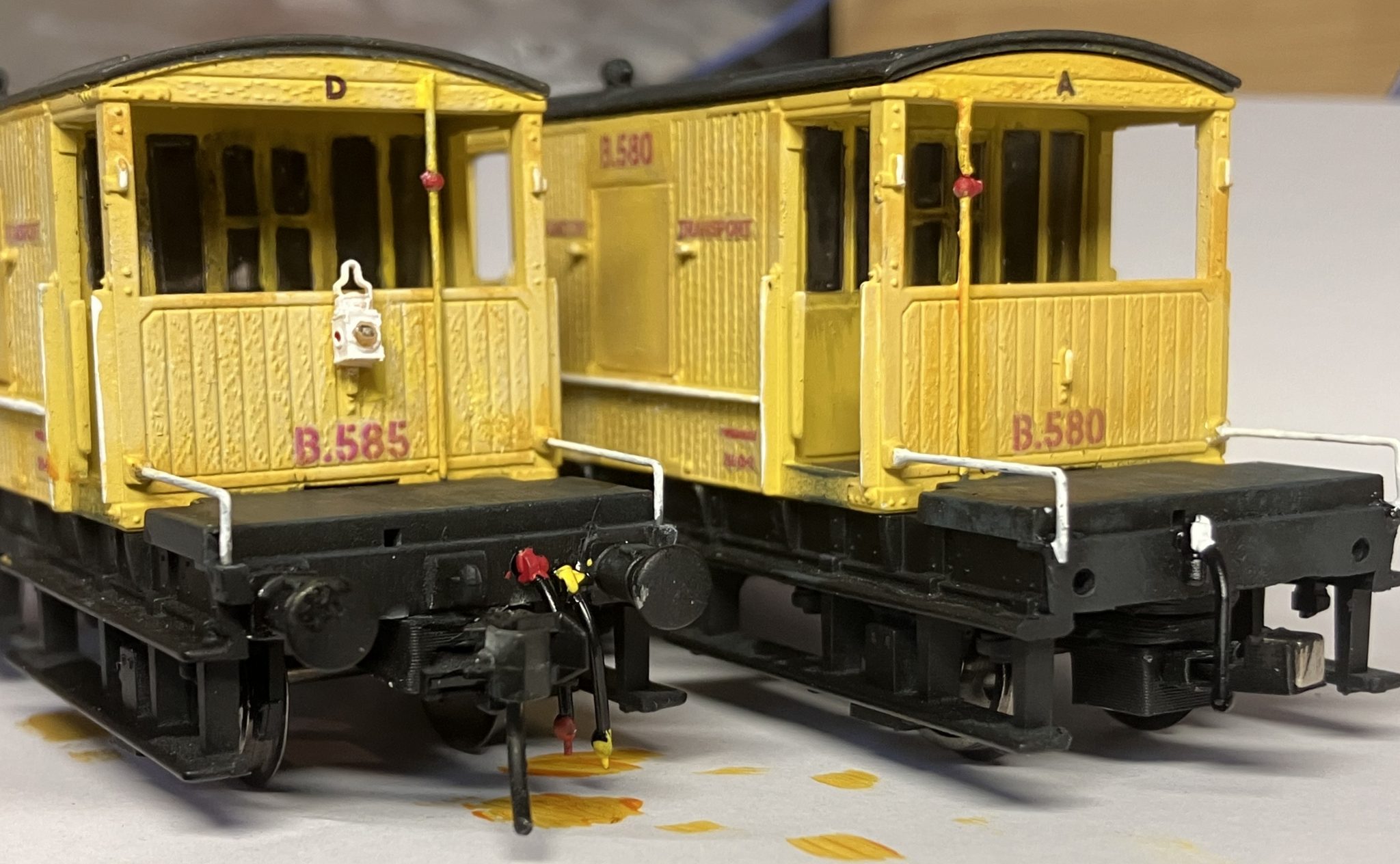
A match wagon is a special kind of wagon designed to overcome the problem of forming trains with rolling stock of incompatible coupling types. They usually have a coupling of one type on one end, with a different type on the other end. B580 and B585 made the trip in 1980 to W.H. Davis in Mansfield, Nottinghamshire to be converted in to Tube Stock match wagons, primarily to assist with the removal and disposal of ’38 Stock cars. B583 and B584 made the same journey to be converted into Surface Stock match wagons, and will be the subject of a similar conversion project in the future. B583 and B584 both survive in preservation at London Transport’s Acton Depot Museum. I photographed both of these in September 2022 when they were in a dilapidated state, though I am happy to declare that both, at the time of writing (September 2023) are at Barrow Hill for restoration. Coincidentally, not a million miles from the place they were originally converted in 1980. A photograph of the prototypes is available here:

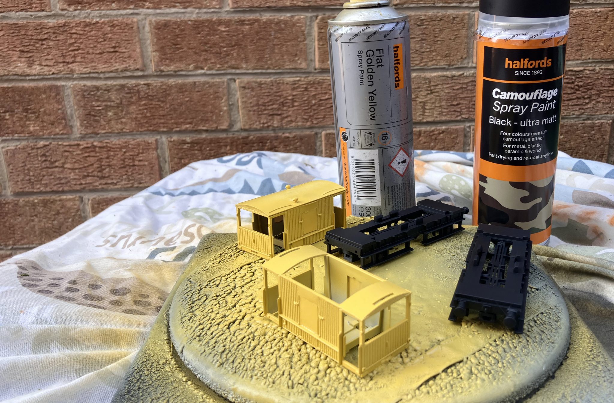
The two models I chose for the conversion are both Hornby. When I built my models of B581 and B582 I used the latest tooling Hornby model with the wire handrails and metal lamp irons. However, for this I struggled to find a pair at the right price for chopping so instead turned my efforts in to sourcing two donors of a slightly elder vintage. Still good models, just lacking a few refinements like NEM pockets and wire handrails. A quick shopping spree on Ebay sourced two Hornby items and two Replica models as a job lot for around £30. The two Replica models have been put aside for the B583/584 project later. The first job was to strip down the models as much as possible to aid the conversion and painting. One of them came apart wonderfully, the second one not so as the roof had been glued to the body with liquid cement and wasn’t in any mood to yield. It would have to be masked later! The four handrails that run from the ends to the edge of the weight on the wagon floor needed to be removed carefully as they would be re-used when it came to re-assembly. I managed to secure seven, with just one being sacrificed to the “hungry rug of doom” under my workbench. Thankfully I keep a stock of 0.33mm handrail brass wire.

At this point, I can reveal why I needed Hornby items for this project. The side lookout duckets on the Hornby model are only held in with two little spigots and come off really easily. Both B580 and B585 had their duckets removed during conversion and plated over with what appears to be sheet steel plate in the one and only photograph I can source of them. At this point I should also point out that the purists amongst you may balk at this conversion, as source material is very hard to come by. I will have got some bits wrong, and for that I can only apologise.
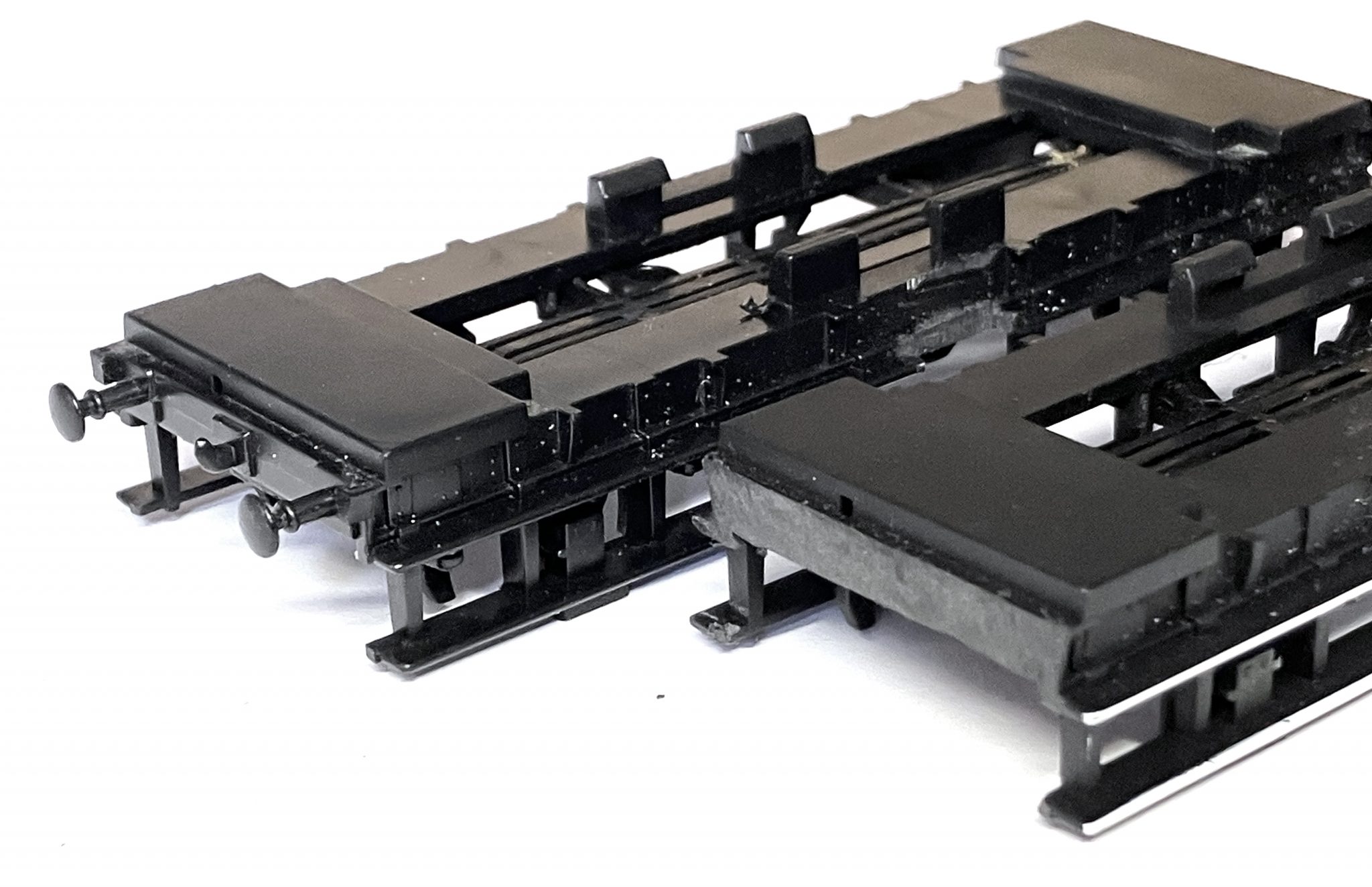
As one end of the van had their buffers and coupling hook removed, this was done using a sharp scalpel and sanding sticks to take the bufferbeam back to being flush. The original spindly Hornby buffers were also removed from the other end and replaced with MJT cast whitemetal items of the thicker BR pattern.
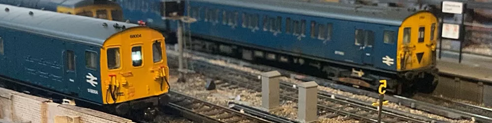
Before I removed the wheels, I took the opportunity to install NEM coupling pockets to the underside of the chassis moulding. On my layout “Atherstone Court”, these two vans will form a rake along with Class 25 25306 (which was loaned to LT for assessment with a view to purchase) and a ’59 Stock motor car. The ’59 car is a modified EFE item with magnetic couplings, chosen for their small size and low profile as they sit low very close to the fourth rail. On the match van there needed to be a low magnetic coupling on the “non-buffered” end and a standard height coupling on the other “buffered” end for coupling to 25306. Apologies for the shameless plug, but I utilised my own brand of 3D printed NEM pockets for this along with Plasticard shims to pack them out to the correct height. These are available to buy on Ebay for anyone needing to convert old rolling stock to modern standards. End of gratuitous plug, sorry.
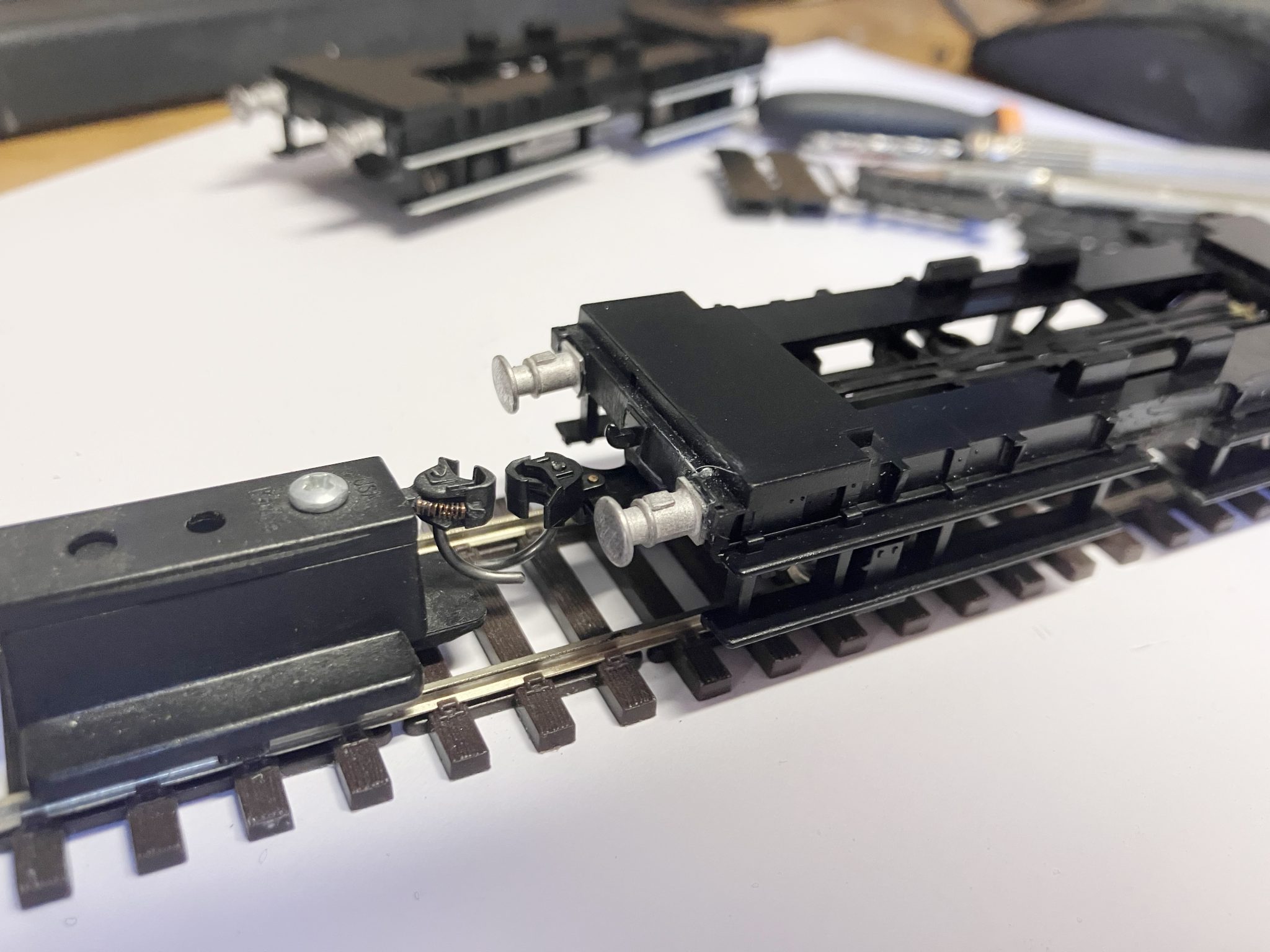

With the coupling heights set, the wheels were removed and discarded. My preference is to use metal wheels on all rolling stock, though it is essential on these vans as both were to be fitted with working tail lamps which take current feeds from the track.
At this point, very minor alterations were made to the chassis. On the “tube stock end”, holes were drilled in the bufferbeam where the original buffer shank would have passed through. On the prototypes, no effort was made to cover these holes. They were simply left along with the eight bolt holes which secured the buffer stock backplate to the bufferbeam. For some reason, during the conversion, the centre section of the long side steps appears to have been removed directly beneath the lookout duckets, so these were duly chopped out using a razor saw.
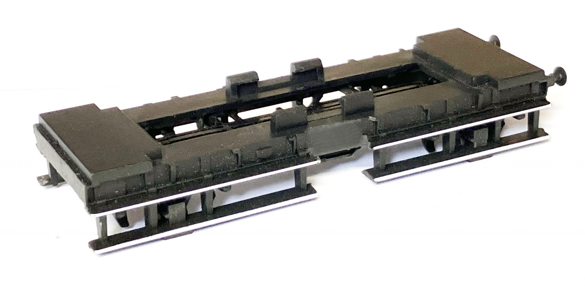
With the chassis complete except for vac and air pipe detailing, both were given a coat of Halfords red acrylic primer and after 24 hours, three light coats of Halfords Camouflage Black ultra matt paint.
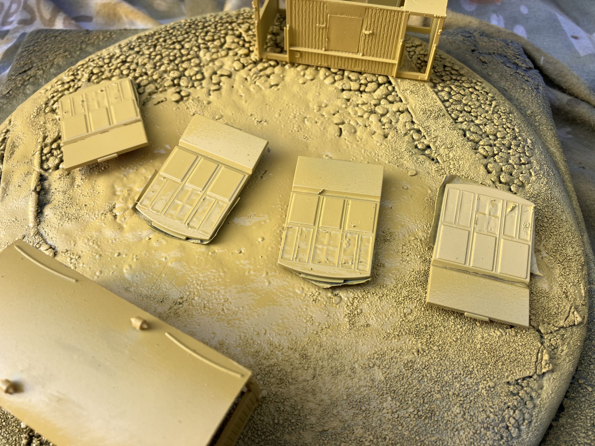
With attention now turning to the body, there was very little to do. Firstly, all roof detail was removed apart from the rain strips. Both ventilators and the stovepipe were sliced off and sanded down to the roof profile. There are two reasons why I did this. The first being that Hornby’s “half relief” representations of the torpedo vents are too small and also facing the wrong way, and it appears that the stove / pipe may have been removed during the conversion. If anyone can confirm or deny this I’d love to hear from you please. The plate above the duckets was carefully filed down flush with the wooden planking and the ducket apertures plated over with 20thou Plasticard. New torpedo vents were added from my own 3D printed items (MJT also produce whitemetal cast items) and the bodies put aside for cleaning and painting.
Both bodies were cleaned with warm water with a few drops of washing up liquid to help remove any greasy finger marks. I used an old toothbrush to remove any sanding / filing debris from the gaps in the wooden planks, being careful not to break the delicate 3D printed torpedo vents
While the bodies dried in the fortunately timed rare UK 30 degree temperatures, I took the opportunity to mask up the inner ends of the bodies so I could spray them yellow without running the glass. Hornby appear to screen print the body colour on to a clear plastic moulding (I may be wrong) which results in a wonderfully crisp and flush glazed piece, but it presents a nightmare for anyone wanting to repaint them. Patience and care was needed here which is unfortunate as I struggle with both as I turn 50. Every pane of glass needed to be masked using Humbrol Maskol. This proved to be quite a challenge, as in the hot summer temperatures it started to dry almost as soon as it vacated the brush.
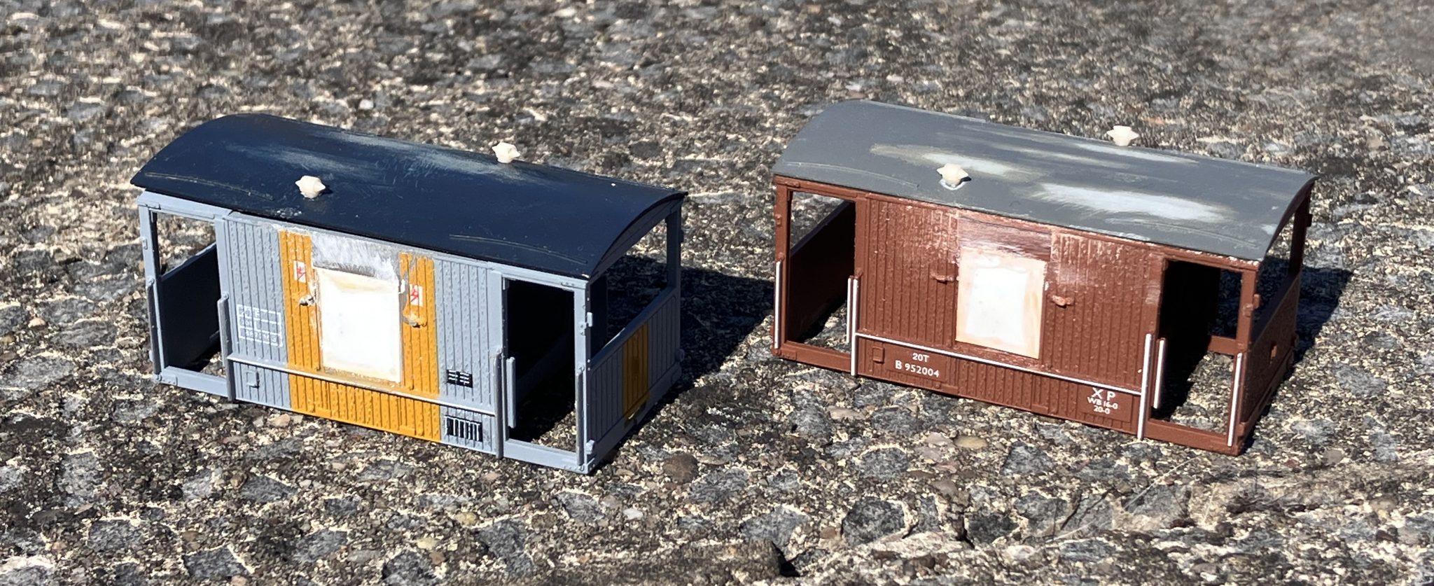
For the LT Engineers Yellow I turned to the trusty Halfords Fiat Golden Yellow. The same shade I use for pre-1984 warning panels and also BR Engineers Stock Yellow. As the bodywork was going to be “sun faded” later, I wasn’t going to get too hung up on colour matching. I’m normally fanatical about such things as I’ve worked in print and colour management since 1989, but I turned a blind eye in this case.
Once three light coats of yellow paint were applied, the roofs were given a single light coat of grey primer and then two coats of Humbrol acrylic Tank Grey. The yellow at this point was a rather off-putting glossy finish, which looked awful but was essential for the next stage when it came to applying transfers. I have to admit I rarely buy transfers. I only buy transfers for numbering locomotives. I am very fortunate to work in an industry where I have access to companies with UV inkjet machines that can print white ink. I’m also fortunate to have around 30 years experience creating print-ready artwork so being able to do this is a massive boost to any project. I have a feeling that transfers for these vans are commercially available, possibly from Railtec, but please do not quote me on that. I personally source my waterslide decal paper from China for two reasons. The first being the availability of blue-back paper in the UK and the second being the questionable reliability of UK vendors of blue-backed paper.
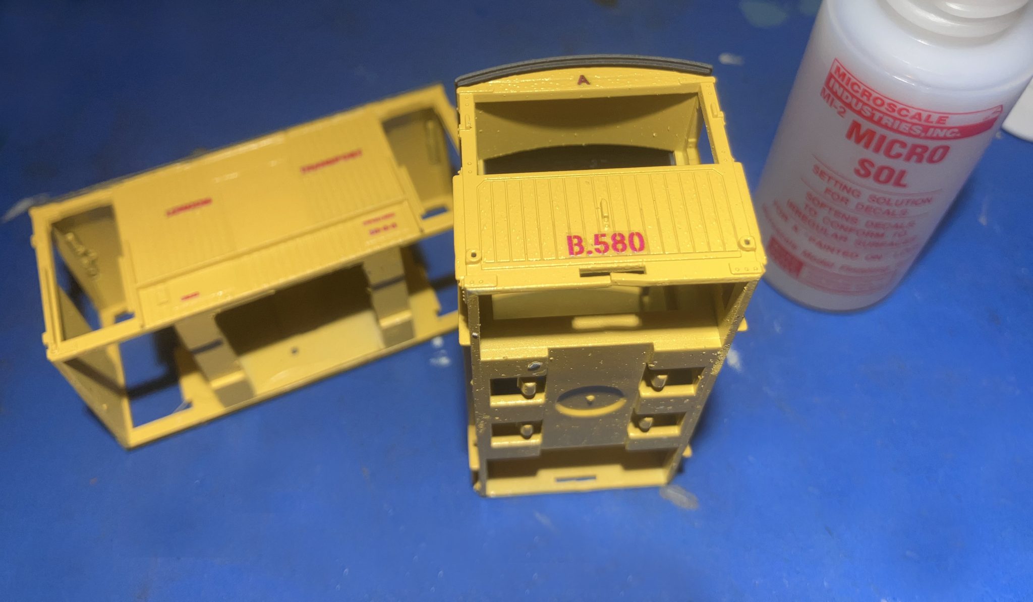
After leaving the decals 48 hours to dry entirely, the bodies were then matt varnished using Humbrol Acrylic varnish from a rattle can. All Maskol was removed from the inner ends and any stray paint removed carefully from the glazing with a cotton bud soaked in Valejo Airbrush Cleaner.
At this point, I made up and fitted homemade stay-alive units for the tail lamps and placed these inside the van bodies. The stay-alives were then soldered to a red LED housed inside a lightproof box, which provides illumination for the tail lamp. A stay-alive unit is a very simple collection of electronic components that will keep an LED lit even if the power source is interrupted by dirty track or insulated point frogs etc. I will not go in to detail of how I make these here, but I will produce a separate article to demonstrate how you can make a whole batch of these for a fraction of the cost of a commercial item. They are really simple and cheap to make.
I also fitted one of my own hollow-bodied tail lamps to the “buffered end” of the vans and thread fibreoptic cable to the inside of the van for connecting to the red LED lightbox. Doing it this way avoids the need for fiddly nano LEDs and provides a very discreet method of producing a very compact illuminated tail lamp.
With the LEDs, stay-alives and fibreoptics fitted, the bodies were re-assembled and clipped back on the chassis, As I had to remove the centre section of the main body floors to get the stay-alives in, a small amount of PVA glue was run along the bottom edge of the body to help it adhere to the chassis moulding. I avoided superglue in case I ever need to remove the bodies for maintenance to the LEDs or stay-alives (highly unlikely). Romford pinpoint 12.5mm wheels were fitted and given a shine with a glass-fibre burnishing brush. A spot of oil was applied to each bearing to aid free-running.
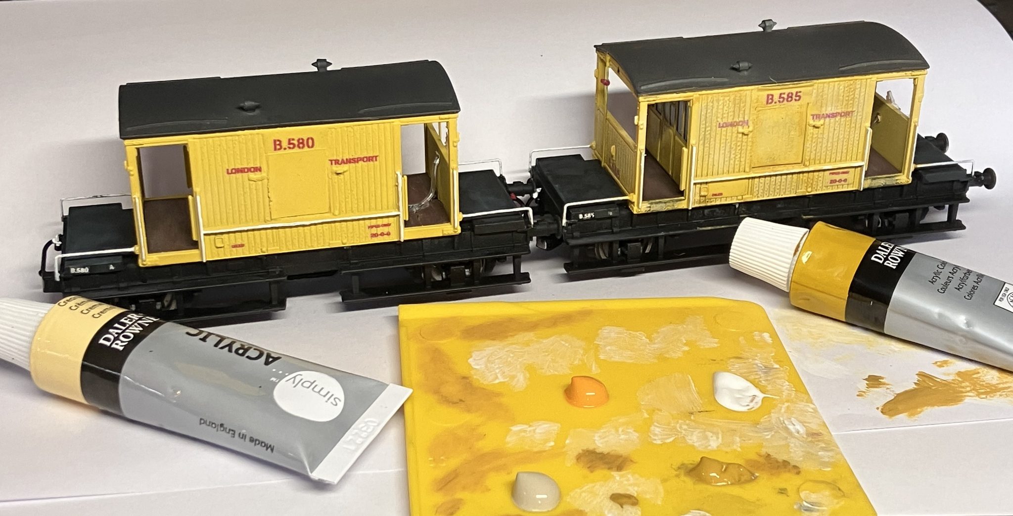
With the vans now largely complete, the paintwork needed fading, as yellow painted wood and the British weather don’t co-exist nicely. I am actually experimenting with a technique which is new to me, which I have successfully (I hope) applied to these, 25306, and an engineer’s four-wheeled PMV. The way I approach this is to use a flat painbrush dry-loaded with cheap artist’s acrylic paint. I mix two shades, one slightly lighter than the base colour, and one slightly darker / dirtier. I then carefully build up areas of faded paintwork by dry-brushing any areas susceptible to fading. In the case of these two vans, any areas exposed to the elements and painted wood. If you observe, painted wood tends to fade, crack, and peel more readily than metals of the same colour, an effect I have tried to capture here.
The only detailing left to do now was to add high-level “through pipes” for the air brakes with their respective valves, and add bufferbeam detail pipework. The air pipes were made from 0.5mm brass rod and one of my own 3D printed “pipe clamps” which I originally created for roof conduits on EMUs. A brass handrail knob would have served the same purpose. Bufferbeam pipework was added from the excellent Replica Railways range.
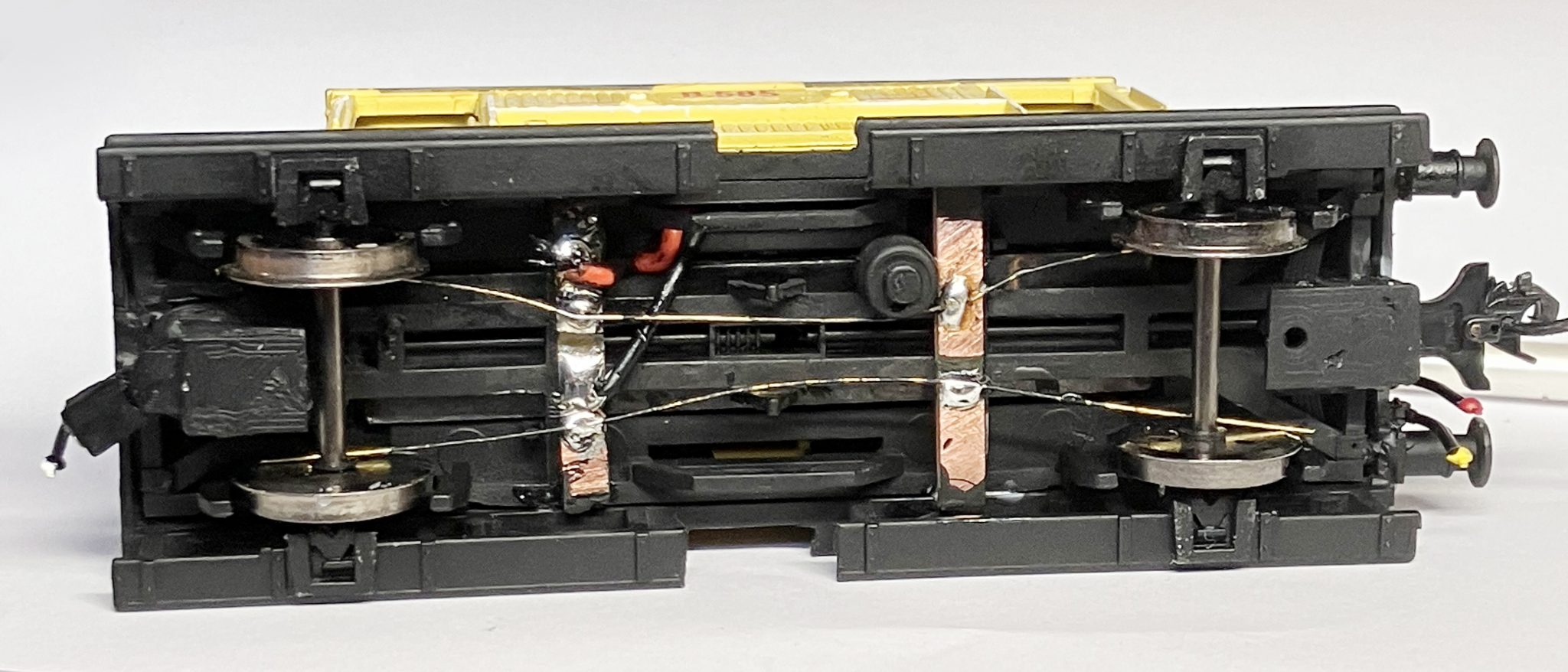
All that remained now was to add electrical pickups to the underside and connect these to the stay-alive input wires.
I stuck with the tried and tested brass wiper method as it has served me well for years. I personally use 0.33m brass handrail wire soldered to “gapped” copper-clad PCB strip.
This was a very enjoyable project completed in a weekend. As I now have four of the LT 20 ton brakes, it would be remis of me not to model the other two, so B583 and B584 will follow in due course once I have some CO/CP or R Stock surface trains to measure the coupling heights against.